NEC 1905
1905
"NATIONAL ELECTRICAL CODE."
RULES AND REQUIREMENTS
OF THE
National Board of Fire Underwriters
FOR THE INSTALLATION OF
ELECTRIC WIRING
AND
APPARATUS
As Recommended by the
UNDERWRITERS' NATIONAL ELECTRIC ASSOCIATION
EDITION OF 1905
The National Electrical Code was originally drawn in 1897 as the result of the united efforts of the various Insurance, Electrical, Architectural and allied interests which through the National Conference on Standard Electrical Rules, composed of delegates from various National Associations, unanimously voted to recommend it to their respective associations for approval or adoption; and is here presented by the National Board of Fire Underwriters with the various amendments and additions which have been made since that time by them.
The following is a list of the Associations composing the National Conference on Standard Electrical Rules:—
AMERICAN INSTITUTE OF ARCHITECTS, AMERICAN INSTITUTE OF ELECTRICAL ENGINEERS. AMERICAN SOCIETY OF MECHANICAL ENGINEERS. AMERICAN INSTITUTE OF MINING ENGINEERS. AMERICAN STREET RAILWAY ASSOCIATION. ASSOCIATED FACTORY MUTUAL FIRE Ins. Co's. ASSOCIATION OF EDISON ILLUMINATING COMPANIES, INTERNATIONAL ASSOCIATION OF FIRE ENGINEERS. INTERNATIONAL ASSOCIATION OF MUNICIPAL ELECTRICIANS. NATIONAL BOARD OF FIRE UNDERWRITERS. NATIONAL ELECTRIC LIGHT ASSOCIATION. NATIONAL ELECTRICAL CONTRACTORS' ASSOCIATION. UNDERWRITERS' NATIONAL ELECTRIC ASSOCIATION.
GENERAL PLAN
GOVERNING THE ARRANGEMENT OF RULES.
CLASS A.—STATIONS AND DYNAMO ROOMS. Includes Central Stations; Dynamo, Motor, and Storage-Battery Rooms; Transformer Substations, etc. Rules 1 to 11.
CLASS B.—OUTSIDE WORK, all systems and voltages. Rules 12 to 13 A.
CLASS C.-INSIDE WORK :— General Rules, all systems and voltages. Rules 14 to 17. Constant-Current Systems. Rules 18 to 20. Constant-Potential Systems :— General Rules, all voltages. Rules 21 to 23. Low-Potential Systems, 550 volts or less. Rules 24 to 34. High-Potential Systems, 550 to 3500 volts. Rules 35 to 37. Extra-High-Potential Systems, over 3500 volts. Rules 38 and 39.
CLASS D.—FITTINGS, MATERIALS, AND DETAILS OF CONSTRUCTION, all systems and voltages. Rules 40 to 63.
CLASS E.—MISCELLANEOUS. Rules 64 to 67.
CLASS F.—MARINE WORK. Rules 68 to 83.
GENERAL SUGGESTIONS.
In all electric work, conductors, however well insulated, should always be treated as bare, to the end that under no conditions, existing or likely to exist, can a ground or short circuit occur, and so that all leakage from conductor to conductor, or between conductor and ground, may be reduced to the minimum.
In all wiring special attention must be paid to the mechanical execution of the work. Careful and neat running, connecting, soldering, taping of conductors, and securing and attaching of fittings, are specially conducive to security and efficiency, and will be strongly insisted on.
In laying out an installation, except for constant-current systems, every reasonable effort should be made to secure distribution centers located in easily accessible places, at which points the cut-outs and switches controlling the several branch circuits can be grouped for convenience and safety of operation. The load should be divided as evenly as possible among the branches, and all complicated and unnecessary wiring avoided.
The use of wire-ways for rendering concealed wiring permanently accessible is most heartily indorsed and recommended; and this method of accessible concealed construction is advised for general use.
Architects are urged, when drawing plans and specifications, to make provision for the channeling and pocketing of buildings for electric light or power wires.
Class A.
STATIONS AND DYNAMO ROOMS.
Includes Central Stations, Dynamo, Motor and Storage-Battery Rooms, Transformer Substations, Etc.
1. Generators.
a. Must be located in a dry place.
b. Must never be placed in a room where any hazardous process is carried on, nor in places where they would be exposed to inflammable gases or flyings of combustible materials.
c. Must be thoroughly insulated from the ground wherever feasible. Wooden base-frames used for this purpose, and wooden floors which are depended upon for insulation where, for any reason, it is necessary to omit the base-frames, must be kept filled to prevent absorption of moisture, and must be kept clean and dry.
Where frame insulation is impracticable, the Inspection Department having jurisdiction may, in writing, permit its omission, in which case the frame must be permanently and effectively grounded.
d. Constant potential generators, except alternating current machines and their exciters, must be protected from excessive current by safety fuses or equivalent devices of approved design.
e. Must each be provided with a waterproof cover.
f. Must each be provided with a name-plate, giving the maker's name, the capacity in volts and amperes, and the normal speed in revolutions per minute.
g. Terminal blocks when used on generators must be made of approved non-combustible, non-absorptive insulating material, such as slate, marble or porcelain.
2. Conductors.
From generators to switchboards, rheostats or other instruments, and thence to outside lines.
a. Must be in plain sight or readily accessible.
b. Must have an approved insulating covering as called for by rules in Class "C" for similar work, except that in central stations, on exposed circuits, the wire which is used must have a heavy braided, non-combustible outer covering. Bus bars may be made of bare metal.
c. Must be kept so rigidly in place that they cannot come in contact.
d. Must in all other respects be installed with the same precautions as required by rules in Class "C" for wires carrying a current of the same volume and potential.
e. In wiring switchboards, the ground detector, voltmeter, pilot lights and potential transformers must be connected to a circuit of not less than No. 14 B. & S. gage wire that is protected by an approved fuse, this circuit is not to carry over 660 watts.
3. Switchboards.
a. Must be so placed as to reduce to a minimum the danger of communicating fire to adjacent combustible material.
b. Must be made of non-combustible material or of hardwood in skeleton form, filled to prevent absorption of moisture.
c. Must be accessible from all sides when the connections are on the back, but may be placed against a brick or stone wall when the wiring is entirely on the face.
d. Must be kept free from moisture.
e. On switchboards the distances between bare live parts of opposite polarity must be made as great as practicable, and must not be less than those given for tablet-boards (see No. 53 A).
4. Resistance Boxes and Equalizers.
(For construction rules, see No. 60.)
a. Must be placed on a switchboard or, if not thereon, at a distance of at least a foot from combustible material, or separated therefrom by a non-combustible, non-absorptive, insulating material, such as slate or marble.
b. Where protective resistances are necessary in connection with automatic rheostats, incandescent lamps may be used, provided that they do not carry or control the main current nor constitute the regulating resistance of the device. When so used, lamps must be mounted in porcelain receptacles upon non-combustible supports, and must be so arranged that they cannot have impressed upon them a voltage greater than that for which they are rated. They must in all cases be provided with a name-plate, which shall be permanently attached beside the porcelain receptacle or receptacles and stamped with the candle-power and voltage of the lamp or lamps to be used in each receptacle.
c. Wherever insulated wire is used for connections between a rheostat and its contact plate, the insulation must be slow burning (see No. 43). For large field rheostats and similar resistances, where the contact plates are not mounted upon them, the connecting wires may be run together in groups so arranged that the maximum difference of potential between any two wires in a group shall not exceed 75 volts. Each group of wires must either be mounted on non-combustible, non-absorptive insulators giving at least 4 inch separation from surface wired over, or, where it is necessary to protect the wires from mechanical injury or moisture, be run in approved lined conduit or equivalent.
5. Lightning Arresters.
(For construction rules, see No. 63.)
a. Must be attached to each wire of every overhead circuit connected with the station.
b. Must be located in readily accessible places away from combustible materials, and as near as practicable to the point where the wires enter the building. In all cases, kinks, coils and sharp bends in the wires between the arresters and the outdoor lines must be avoided as far as possible.
c. Must be connected with a thoroughly good and permanent ground connection by metallic strips or wires having a conductivity not less than that of a No. 6 B. & S. gage copper wire, which must be run as nearly in a straight line as possible from the arresters to the ground connection. Ground wires for lightning arresters must not be attached to gas pipes within the buildings.
d. All choke coils or other attachments, inherent to the lightning protection equipment, shall have an insulation from the ground or other conductors equal at least to the insulation demanded at other points of the circuit in the station.
6. Care and Attendance.
a. A competent man must be kept on duty where generators are operating.
b. Oily waste must be kept in approved metal cans and removed daily.
7. Testing of Insulation Resistance.
a. All circuits except such as are permanently grounded in accordance with No. 13 A must be provided with reliable ground detectors. Detectors which indicate continuously and give an instant and permanent indication of a ground are preferable. Ground wires from detectors must not be attached to gas pipes within the building.
b. Where continuously indicating detectors are not feasible, the circuits should be tested at least once per day, and preferably oftener.
c. Data obtained from all tests must be preserved for examination by the Inspection Department having jurisdiction.
8. Motors.
a. Must be thoroughly insulated from the ground wherever feasible. Wooden base-frames used for this purpose, and wooden floors which are depended upon for insulation, where, for any reason, it is necessary to omit the base-frames, must be kept filled to prevent absorption of moisture, and must be kept clean and dry. Where frame insulation is impracticable, the Inspection Department having jurisdiction may, in writing, permit its omission, in which case the frame must be permanently and effectively grounded.
b. Must be wired with the same precautions as required by rules in class "C" for wires carrying a current of the same volume and potential.
c. Each motor and resistance box must be protected by a cut-out and controlled by a switch (see No. 17 a), said switch plainly indicating whether "on" or "off." With motors of one-fourth horse power or less, on circuits where the voltage does not exceed 300, No. 21 d must be complied with, and single pole switches may be used as allowed in No. 22 c. The switch and rheostat must be located within sight of the motor, except in cases where special permission to locate them elsewhere is given, in writing, by the Inspection Department having jurisdiction.
d. Must have their rheostats or starting boxes located so as to conform to the requirements of No. 4.
e. Must not be run in series-multiple or multiple-series, except on constant-potential systems, and then only by special permission of the Inspection Department having jurisdiction.
f. Must be covered with a waterproof cover when not in use, and, if deemed necessary by the Inspection Department having jurisdiction, must be enclosed in an approved case.
g. Must, when combined with ceiling fans, be hung from insulated hooks, or else there must be an insulator interposed between the motor and its support.
h. Must each be provided with a name-plate, giving the maker's name, the capacity in volts and amperes, and the normal speed in revolutions per minute.
i. Terminal blocks when used on motors must be made of approved non-combustible, non-absorptive, insulating material, such as slate, marble or porcelain.
9. Railway Power Plants.
a. Each feed wire before it leaves the station must be equipped with an approved automatic circuit-breaker (see No. 52) or other device, which will immediately cut off the current in case of an accidental ground. This device must be mounted on a fireproof base, and in full view and reach of the attendant.
10. Storage or Primary Batteries.
a. When current for light and power is taken from primary or secondary batteries, the same general regulations must be observed as apply to similar apparatus fed from dynamo generators developing the same difference of potential.
b. Storage battery rooms must be thoroughly ventilated.
c. Special attention is directed to the rules for wiring in rooms where acid fumes exist (see No. 24, i to k).
d. All secondary batteries must be mounted on non-absorptive, non-combustible insulators, such as glass or thoroughly vitrified and glazed porcelain.
e. The use of any metal liable to corrosion must be avoided in cell connections of secondary batteries.
11. Transformers.
(For construction rules, see No. 62.)
(See also Nos. 13, 13 A, 36.)
a. In central or sub-stations the transformers must be so placed that smoke from the burning out of the coils or the boiling over of the oil (where oil filled cases are used) could do no harm.
Class B.
OUTSIDE WORK.
(Light, Power and Heat. For Signaling Systems, see Class E.)
ALL SYSTEMS AND VOLTAGES.
12. Wires.
a. Service wires must have an approved rubber insulating covering (see No. 41). Line wires, other than services, must have an approved weatherproof or rubber insulating covering (see Nos. 41 and 44). All tie wires must have an insulation equal to that of the conductors they confine.
b. Must be so placed that moisture cannot form a cross connection between them, not less than a foot apart, and not in contact with any substance other than their insulating supports. Wooden blocks to which insulators are attached must be covered over their entire surface with at least two coats of waterproof paint.
c. Must be at least seven feet above the highest point of flat roofs, and at least one foot above the ridge of pitched roofs over which they pass or to which they are attached.
d. Must be protected by dead insulated guard irons or wires from possibility of contact with other conducting wires or substances to which current may leak. Special precautions of this kind must be taken where sharp angles occur, or where any wires might possibly come in contact with electric light or power wires.
e. Must be provided with petticoat insulators of glass or porcelain. Porcelain knobs or cleats and rubber hooks will not be approved.
f. Must be so spliced or joined as to be both mechanically and electrically secure without solder. The joints must then be soldered, to insure preservation, and covered with an insulation equal to that on the conductors.
g. Must, where they enter buildings, have drip loops outside, and the holes through which the conductors pass must be bushed with non-combustible, non-absorptive insulating tubes slanting upward toward the inside.
h. Electric light and power wires must not be placed on the same cross-arm with telegraph, telephone or similar wires, and when placed on the same pole with such wires the distance between the two inside pins of each cross-arm must not be less than twenty-six inches.
i. The metallic sheaths to cables must be permanently and effectively connected to "earth."
Trolley Wires.
j. Must not be smaller than No. 0 B. & S. gage copper or No. 4 B. & S. gage silicon bronze, and must readily stand the strain put upon them when in use.
k. Must have a double insulation from the ground. In wooden pole construction the pole will be considered as one insulation.
l. Must be capable of being disconnected at the power plant, or of being divided into sections, so that, in case of fire on the railway route, the current may be shut off from the particular section and not interfere with the work of the firemen. This rule also applies to feeders.
m. Must be safely protected against accidental contact where crossed by other conductors.
Ground Return Wires.
n. For the diminution of electrolytic corrosion of underground metal work, ground return wires must be so arranged that the difference of potential between the grounded dynamo terminal and any point on the return circuit will not exceed twenty-five volts.
12 A. Constant-Potential Pole Lines, Over 5,000 Volts.
(Overhead lines of this class unless properly arranged may increase the fire loss from the following causes :—
Accidental crosses between such lines and low-potential lines may allow the high-voltage current to enter buildings over a large section of adjoining country. Moreover, such high-voltage lines, if carried close to buildings, hamper the work of firemen in case of fire in the building. The object of these rules is so to direct this class of construction that no increase in fire hazard will result, while at the same time care has been taken to avoid restrictions which would unreasonably impede progress in electrical development.
It is fully understood that it is impossible to frame rules which will cover all conceivable cases that may arise in construction work of such an extended and varied nature, and it is advised that the Inspection Department having jurisdiction be freely consulted as to any modification of the rules in particular cases.)
a. Every reasonable precaution must be taken in arranging routes so as to avoid exposure to contacts with other electric circuits. On existing lines, where there is a liability to contact, the route should be changed by mutual agreement between the parties in interest wherever possible.
b. Such lines should not approach other pole lines nearer than a distance equal to the height of the taller pole line, and such lines should not be on the same poles with other wires, except that signalling wires used by the Company operating the high-pressure system, and which do not enter property other than that owned or occupied by such Company, may be carried over the same poles.
c. Where such lines must necessarily be carried nearer to other pole lines than is specified in Section b above, or where they must necessarily be carried on the same poles with other wires, extra precautions to reduce the liability of a breakdown to a minimum must be taken, such as the use of wires of ample mechanical strength, widely spaced cross-arms, short spans, double or extra heavy cross-arms, extra heavy pins, insulators, and poles thoroughly supported. If carried on the same poles with other wires, the high-pressure wires must be carried at least three feet above the other wires.
d. Where such lines cross other lines, the poles of both lines must be of heavy and substantial construction. Whenever it is feasible, end-insulator guards should be placed on the cross-arms of the upper line. If the high-pressure wires cross below the other lines, the wires of the upper line should be dead-ended at each end of the span to double-grooved, or to standard transposition insulators, and the line completed by loops.
One of the following forms of construction must then be adopted:—
- The height and length of the cross-over span may be made such that the shortest distance between the lower cross-arms of the upper line and any wire of the lower line will be greater than the length of the cross-over span, so that a wire breaking near one of the upper pins would not be long enough to reach any wire of the lower line. The high-pressure wires should preferably be above the other wires.
- A joint pole may be erected at the crossing point, the high-pressure wires being supported on this pole at least three feet above the other wires. Mechanical guards or supports must then be provided, so that in case of the breaking of any upper wire, it will be impossible for it to come into contact with any of the lower wires.
- Whenever neither of the above methods is feasible, a screen of wires should be interposed between the lines at the cross-over. This screen should be supported on high tension insulators or grounded and should be of such construction and strength as to prevent the upper wires from coming into contact with the lower ones.
e. When it is necessary to carry such lines near buildings, they must be at such height and distance from the building as not to interfere with firemen in event of fire; therefore, if within 25 feet of a building, they must be carried at a height not less than that of the front cornice, and the height must be greater than that of the cornice, as the wires come nearer to the building in accordance with the following table:—
| Distance of wire from building (Feet) | Elevation of wire above cornice of building (Feet) |
|---|---|
| 25 | 0 |
| 20 | 2 |
| 15 | 4 |
| 10 | 6 |
| 5 | 8 |
| 2½ | 9 |
13. Transformers.
(For construction rules, see No. 62.) (See also Nos. 11, 13 A and 36.)
a. Must not be placed inside of any building, excepting central stations and sub-stations, unless by special permission of the Inspection Department having jurisdiction.
b. Must not be attached to the outside walls of buildings, unless separated therefrom by substantial supports.
13 A. Grounding Low-Potential Circuits.
The grounding of low-potential circuits under the following regulations is only allowed when such circuits are so arranged that under normal conditions of service there will be no passage of current over the ground wire.
Direct-Current 3-Wire Systems.
a. Neutral wire may be grounded, and when grounded the following rules must be complied with:—
- Must be grounded at the Central Station on a metal plate buried in coke beneath permanent moisture level, and also through all available underground water and gas-pipe systems.
- In underground systems the neutral wire must also be grounded at each distributing box through the box.
- In overhead systems the neutral wire must be grounded every 500 feet, as provided in Sections c, e, f and g.
Alternating-Current Secondary Systems.
b. Transformer secondaries of distributing systems should preferably be grounded, and when grounded, the following rules must be complied with :—
- The grounding must be made at the neutral point or wire, whenever a neutral point or wire is accessible.
- When no neutral point or wire is accessible, one side of the secondary circuit may be grounded, provided the maximum difference of potential between the grounded point and any other point in the circuit does not exceed 250 volts.
- The ground connection must be at the transformer as provided in sections d, e, f, g, and when transformers feed systems with a neutral wire, the neutral wire must also be grounded at least every 250 feet for overhead systems, and every 500 feet for underground systems.
Ground Connections.
c. The ground wire in direct-current 3-wire systems must not at Central Stations be smaller than the neutral wire and not smaller than No. 6 B. & S. gage elsewhere.
d. The ground wire in alternating-current systems must never be less than No. 6 B. & S. gage, and must always have equal carrying capacity to the secondary lead of the transformer, or the combined leads where transformers are connected in parallel.
e. The ground wire must be kept outside of buildings, but may be directly attached to the building or pole. The wire must be carried in as nearly a straight line as possible, and kinks, coils and sharp bends must be avoided.
f. The ground connection for Central Stations, transformer substations, and banks of transformers must be made through metal plates buried in coke below permanent moisture level, and connection should also be made to all available underground piping systems including the lead sheath of underground cables.
g. For individual transformers and building services the ground connection may be made as in Section f, or may be made to water or other piping systems running into the buildings. This connection may be made by carrying the ground wire into the cellar and connecting on the street side of meters, main cocks, etc., but connection must never be made to any lead pipes which form part of gas services.
Class C.
INSIDE WORK.
(Light, Power and Heat. For Signaling Systems, see Class E.)
ALL SYSTEMS AND VOLTAGES
GENERAL RULES.
14. Wires.
(For special rules, see Nos. 18, 24, 35, 38 and 39.)
a. Must not be of smaller size than No. 14 B. & S. gage, except as allowed under Nos. 24 v and 45 b.
b. Tie wires must have an insulation equal to that of the conductors they confine.
c. Must be so spliced or joined as to be both mechanically and electrically secure without solder. The joints must then be soldered to insure preservation, and covered with an insulation equal to that on the conductors. Stranded wires must be soldered before being fastened under clamps or binding screws, and whether stranded or solid, when they have a conductivity greater than that of No. 8 B. & S. gage they must be soldered into lugs for all terminal connections.
d. Must be separated from contact with walls, floors, timbers or partitions through which they may pass by non-combustible, non-absorptive insulating tubes, such as glass or porcelain, except as provided in No. 24 u.
e. Must be kept free from contact with gas, water or other metallic piping, or any other conductors or conducting material which they may cross, by some continuous and firmly fixed non-conductor, creating a permanent separation. Deviations from this rule may sometimes be allowed by special permission.
f. Must be so placed in wet places that an air space will be left between conductors and pipes in crossing, and the former must be run in such a way that they cannot come in contact with the pipe accidentally. Wires should be run over, rather than under, pipes upon which moisture is likely to gather or which, by leaking, might cause trouble on a circuit.
g. The installation of electrical conductors in wooden moulding or where supported on insulators in elevator shafts will not be approved, but conductors may be installed in such shafts if encased in approved metal conduits.
15. Underground Conductors.
a. Must be protected against moisture and mechanical injury where brought into a building, and all combustible material must be kept from the immediate vicinity.
b. Must not be so arranged as to shunt the current through a building around any catch-box.
c. Where underground service enters building through tubes, the tubes shall be tightly closed at outlets with asphaltum or other non-conductor, to prevent gases from entering the building through such channels.
d. No underground service from a subway to a building shall supply more than one building except by written permission from the Inspection Department having jurisdiction.
16. Table of Carrying Capacity of Wires.
a. The following table, showing the allowable carrying capacity of copper wires and cables of ninety-eight per cent conductivity, according to the standard adopted by the American Institute of Electrical Engineers, must be followed in placing interior conductors.
| Table A. | Table B. | ||
|---|---|---|---|
| Rubber Insulation. | Other Insulations. | ||
| See No. 41. | See Nos. 42 to 44. | ||
| B. & S. G. | Amperes. | Amperes. | Circular Mils. |
| 18 | 3 | 5 | 1,624 |
| 16 | 6 | 8 | 2,583 |
| 14 | 12 | 16 | 4,107 |
| 12 | 17 | 23 | 6,530 |
| 10 | 24 | 32 | 10,380 |
| 8 | 33 | 46 | 16,510 |
| 6 | 46 | 65 | 26,250 |
| 5 | 54 | 77 | 33,100 |
| 4 | 65 | 92 | 41,740 |
| 3 | 76 | 110 | 52,630 |
| 2 | 90 | 131 | 66,370 |
| 1 | 107 | 156 | 83,690 |
| 0 | 127 | 185 | 105,500 |
| 00 | 150 | 220 | 133,100 |
| 000 | 177 | 262 | 167,800 |
| 0000 | 210 | 312 | 211,600 |
| Circular Mils. | |||
| 200,000 | 200 | 300 | |
| 300,000 | 270 | 400 | |
| 400,000 | 330 | 500 | |
| 500,000 | 390 | 590 | |
| 600,000 | 450 | 680 | |
| 700,000 | 500 | 760 | |
| 800,000 | 550 | 840 | |
| 900,000 | 600 | 920 | |
| 1,000,000 | 650 | 1,000 | |
| 1,100,000 | 690 | 1,080 | |
| 1,200,000 | 730 | 1,150 | |
| 1,300,000 | 770 | 1,220 | |
| 1,400,000 | 810 | 1,290 | |
| 1,500,000 | 850 | 1,360 | |
| 1,600,000 | 890 | 1,430 | |
| 1,700,000 | 930 | 1,490 | |
| 1,800,000 | 970 | 1,550 | |
| 1,900,000 | 1,010 | 1,610 | |
| 2,000,000 | 1,050 | 1,670 |
17. Switches, Cut-outs, Circuit-Breakers, Etc.
(For construction rules, see Nos. 51, 52 and 53.)
a. Must, for constant potential circuits, unless otherwise provided (for exceptions, see No. 8 c and No. 22 c), be so arranged that the cut-outs will protect, and the opening of a switch or circuit-breaker will disconnect, all of the wires; that is, in a two-wire system the two wires, and in a three-wire system the three wires, must be protected by the cut-out and disconnected by the operation of the switch or circuit-breaker.
b. Must not be placed in the immediate vicinity of easily ignitible stuff or where exposed to inflammable gases or dust or to flyings of combustible material.
c. Must, when exposed to dampness, either be enclosed in a waterproof box or mounted on porcelain knobs.
d. Time switches must be enclosed in an iron box or cabinet lined with fire resisting material.
CONSTANT-CURRENT SYSTEMS.
PRINCIPALLY SERIES ARC LIGHTING.
18. Wires.
(See also Nos. 14, 15 and 16.)
a. Must have an approved rubber insulating covering (see No 41).
b. Must be arranged to enter and leave the building through an approved double-contact service switch (see No. 51 b), mounted in a non-combustible case, kept free from moisture, and easy of access to police or firemen.
c. Must always be in plain sight, and never encased, except when required by the Inspection Department having jurisdiction.
d. Must be supported on glass or porcelain insulators, which separate the wire at least one inch from the surface wired over, and must be kept rigidly at least eight inches from each other, except within the structure of lamps, on hanger-boards or in cut-out boxes, or like places, where a less distance is necessary.
e. Must, on side walls, be protected from mechanical injury by a substantial boxing, retaining an air space of one inch around the conductors, closed at the top (the wires passing through bushed holes), and extending not less than seven feet from the floor. When crossing floor timbers in cellars, or in rooms where they might be exposed to injury, wires must be attached by their insulating supports to the under side of a wooden strip not less than one-half an inch in thickness. Instead of the running-boards, guard strips on each side of and close to the wires will be accepted. These strips to be not less than seven-eighths of an inch in thickness and at least as high as the insulators.
19. Series Arc Lamps.
(For construction rules, see No. 57.)
a. Must be carefully isolated from inflammable material.
b. Must be provided at all times with a glass globe surrounding the arc, and securely fastened upon a closed base. Broken or cracked globes must not be used.
c. Must be provided with a wire netting (having a mesh not exceeding one and one-fourth inches) around the globe, and an approved spark arrester (see No. 58), when readily inflammable material is in the vicinity of the lamps, to prevent escape of sparks of carbon or melted copper. It is recommended that plain carbons, not copper-plated, be used for lamps in such places.
d. Where hanger-boards (see No. 56) are not used, lamps must be hung from insulating supports other than their conductors.
e. Lamps when arranged to be raised and lowered, either for carboning or other purposes, shall be connected up with stranded conductors from the last point of support to the lamp, when such conductor is larger than No. 14 B. & S. gage.
20. Incandescent Lamps in Series Circuits.
a. Must have the conductors installed as required in No. 18, and each lamp must be provided with an automatic cut-out.
b. Must have each lamp suspended from a hanger-board by means of rigid tube.
c. No electro-magnetic device for switches and no multiple-series or series-multiple system of lighting will be approved.
d. Must not under any circumstances be attached to gas fixtures.
CONSTANT-POTENTIAL SYSTEMS.
GENERAL RULES—ALL VOLTAGES.
21. Automatic Cut-outs (Fuses and Circuit-Breakers).
(See No. 17, and for construction, Nos. 52 and 53.)
a. Must be placed on all service wires, either overhead or underground, as near as possible to the point where they enter the building and inside the walls, and arranged to cut off the entire current from the building.
b. Must be placed at every point where a change is made in the size of wire [unless the cut-out in the larger wire will protect the smaller (see No. 16)].
c. Must be in plain sight, or enclosed in an approved cabinet (see No. 54), and readily accessible. They must not be placed in the canopies or shells of fixtures.
d. Must be so placed that no set of incandescent lamps requiring more than 660 watts, whether grouped on one fixture or on several fixtures or pendants, will be dependent upon one cut-out. Special permission may be given in writing by the Inspection Department having jurisdiction for departure from this rule in the case of large chandeliers, stage borders, and illuminated signs.
e. The rated capacity of fuses must not exceed the allowable carrying capacity of the wire as given in No. 16. Circuit-breakers must not be set more than 30 per cent above the allowable carrying capacity of the wire, unless a fusible cut-out is also installed in the circuit.
22. Switches.
(See No. 17, and for construction, No. 51.)
a. Must be placed on all service wires, either overhead or underground, in a readily accessible place, as near as possible to the point where the wires enter the building, and arranged to cut off the entire current.
b. Must always be placed in dry, accessible places, and be grouped as far as possible. Single-throw knife switches must be so placed that gravity will tend to open rather than close them. Double-throw knife switches may be mounted so that the throw will be either vertical or horizontal as preferred.
c. Must not be single pole when the circuits which they control supply devices which require over 660 watts of energy, or when the difference of potential is over 300 volts.
d. Where flush switches or receptacles are used, whether with conduit systems or not, they must be enclosed in boxes constructed of iron or steel. No push buttons for bells, gas-lighting circuits, or the like shall be placed in the same wall plate with switches controlling electric light or power wiring.
e. Where possible, at all switch or fixture outlets, a ⅞-inch block must be fastened between studs or floor timbers flush with the back of lathing to hold tubes, and to support switches or fixtures. When this cannot be done, wooden base blocks, not less than ¾-inch in thickness, securely screwed to lathing, must be provided for switches, and also for fixtures which are not attached to gas pipes or conduit.
23. Electric Heaters.
a. Must be protected by a cut-out and controlled by indicating switches arranged as required for electric power devices employing the same current and potential.
b. Must never be concealed, but must at all times be in plain sight.
c. Flexible conductors for smoothing irons and sad irons, and for all devices requiring over 250 watts, must comply with Rule 45, section g.
d. For portable heating devices the flexible conductors must be connected to an approved plug device, so arranged that the plug will pull out and open the circuit in case any abnormal strain is put on the flexible conductor. This device may be stationary, or it may be placed in the cord itself. The cable or cord must be attached to the heating apparatus in such manner that it will be protected from kinking, chafing, or like injury at or near the point of connection.
e. Smoothing irons, sad irons, and other heating appliances that are intended to be applied to inflammable articles, such as clothing, must conform to the above rules, so far as they apply. They must also be provided with an approved stand, on which they should be placed when not in use.
f. Stationary electric heating apparatus, such as radiators, ranges, plate warmers, etc., must be placed in a safe location, isolated from inflammable materials, and be treated as sources of heat.
g. Must each be provided with name-plate, giving the maker's name and the normal capacity in volts and amperes.
LOW-POTENTIAL SYSTEMS.
550 VOLTS OR LESS.
Any circuit attached to any machine, or combination of machines, which develops a difference of potential between any two wires, of over ten volts and less than 550 volts, shall be considered as a low-potential circuit, and as coming under this class, unless an approved transforming device is used, which cuts the difference of potential down to ten volts or less. The primary circuit not to exceed a potential of 3,500 volts unless the primary wires are installed in accordance with the requirements as given in No. 12 A, or are underground.
Before pressure is raised above 300 volts on any previously existing system of wiring, the whole must be strictly brought up to all of the requirements of the rules at date.
24. Wires.
GENERAL RULES.
(See also Nos. 14, 15, and 16.)
a. Must be so arranged that under no circumstances will there be a difference of potential of over 300 volts between any bare metal parts in any distributing switch or cut-out cabinet, or equivalent center of distribution.
b. Must not be laid in plaster, cement, or similar finish, and must never be fastened with staples.
c. Must not be fished for any great distance, and only in places where the inspector can satisfy himself that the rules have been complied with.
d. Twin wires must never be used, except in conduits, or where flexible conductors are necessary.
e. Must be protected on side walls from mechanical injury. When crossing floor timbers in cellars, or in rooms where they might be exposed to injury, wires must be attached by their insulating supports to the under side of a wooden strip, not less than one-half inch in thickness, and not less than three inches in width. Instead of the running-boards, guard strips on each side of and close to the wires will be accepted. These strips to be not less than seven-eighths of an inch in thickness, and at least as high as the insulators.
f. When run in unfinished attics, will be considered as concealed and when run in close proximity to water tanks or pipes, will be considered as exposed to moisture.
SPECIAL RULES.
For Open Work.
In dry places.
g. Must have an approved rubber or "slow-burning weatherproof" insulation (see Nos. 41 and 42).
h. Must be rigidly supported on non-combustible, non-absorptive insulators, which will separate the wires from each other and from the surface wired over in accordance with the following table:—
| Voltage. | Distance from Surface. | Distance between Wires. |
|---|---|---|
| 0 to 300 | ½ inch | 2½ inch |
| 301 to 550 | 1 " | 4 " |
In damp places, or buildings specially subject to moisture or to acid or other fumes liable to injure the wires or their insulation.
i. Must have an approved insulating covering.
j. Must be rigidly supported on non-combustible, non-absorptive insulators, which separate the wire at least one inch from the surface wired over, and must be kept apart at least two and one-half inches for voltages up to 300, and four inches for higher voltages.
k. (Stricken out.)
For Moulding Work
l. Must have an approved rubber insulating covering (see No. 41).
m. Must never be placed in moulding in concealed or damp places, or where the difference of potential between any two wires in the same moulding is over 300 volts.
For Conduit Work.
n. Must have an approved rubber insulating covering (see No. 47).
o. Must not be drawn in until all mechanical work on the building has been, as far as possible, completed. Conductors in vertical conduit risers must be supported within the conduit system in accordance with the following table:— No. 14 to 0 every 100 feet. No. 00 to 4-0 every 80 feet. 0000 to 350,000 C. M. every 60 feet. 350,000 C. M. to 500,000 C. M. every 50 feet. 500,000 C. M. to 750,000 C. M. every 40 feet. 750,000 C. M. every 35 feet. A turn of 90 degrees in the conduit system will constitute a satisfactory support, as per above table.
The following methods of supporting cables are recommended :—
- Junction boxes may be inserted in the conduit system at the required intervals, in which insulating supports of approved type must be installed and secured in a satisfactory manner so as to withstand the weight of the conductors attached thereto, the boxes to be provided with proper covers.
- Cables may be supported in approved junction boxes on two or more insulating supports so placed that the conductors will be deflected at an angle of not less than 90 degrees, and carried a distance of not less than twice the diameter of the cable from its vertical position. Cables so suspended may be additionally secured to these insulators by tie wires. Other methods, if used, must be approved by the Inspection Departments having jurisdiction.
p. Must, for alternating systems, have the two or more wires of a circuit drawn in the same conduit.
For Concealed "Knob and Tube" Work.
q. Must have an approved rubber insulating covering (see No. 41).
r. Must be rigidly supported on non-combustible, non-absorptive insulators which separate the wire at least one inch from the surface wired over. Must be kept at least ten inches apart, and, when possible, should be run singly on separate timbers or studdings. Must be separated from contact with the walls, floor timbers and partitions through which they may pass by non-combustible, non-absorptive insulating tubes, such as glass or porcelain.
s. When, in a concealed knob and tube system, it is impracticable to place any circuit on noncombustible supports of glass or porcelain, approved metal conduit or approved armored cable must be used (see No. 24 t), except that if the difference of potential between the wires is not over 300 volts, and if the wires are not exposed to moisture, they may be fished on the loop system if separately encased throughout in continuous lengths of approved flexible tubing.
t. Mixed concealed knob and tube work as provided for in No. 24 s, must comply with requirements of No. 24 n to p, and No. 25, when conduit is used, and with requirements of No. 24 A, when armored cable is used.
u. Must at all outlets, except where conduit is used, be protected by approved flexible insulating tubing, extending in continuous lengths from the last porcelain support to at least one inch beyond the outlet. In the case of combination fixtures the tubes must extend at least flush with outer end of gas cap.
For Fixture Work
v. Must have an approved rubber insulating covering (see No. 46), and be not less in size than No. 18 B. & S. gage.
w. Supply conductors, and especially the splices to fixture wires, must be kept clear of the grounded part of gas pipes, and, where shells or outlet boxes are used, they must be made sufficiently large to allow the fulfilment of this requirement.
x. Must, when fixtures are wired outside, be so secured as not to be cut or abraded by the pressure of the fastenings or motion of the fixture.
y. Under no circumstances must there be a difference of potential of more than 300 volts between wires contained in or attached to the same fixture.
24 A. Armored Cables.
(For construction rules, see No. 48.)
a. Must be continuous from outlet to outlet or to junction boxes, and the armor of the cable must properly enter and be secured to all fittings.
b. Must be equipped at every outlet with an approved outlet box or plate, as required in conduit work. (See No. 49 A.)
c. Must have the metal armor of the cable permanently and effectively grounded.
d. When installed in so-called fireproof buildings in course of construction or afterwards if concealed, or where it is exposed to the weather, or in damp places such as breweries, stables, etc., the cable must have a lead covering at least one thirty-second inch in thickness placed between the outer braid of the conductors and the steel armor.
e. Where entering junction boxes, and at all other outlets, etc., must be provided with approved terminal fittings which will protect the insulation of the conductors from abrasion, unless such junction or outlet boxes are specially designed and approved for use with the cable.
f. Junction boxes must always be installed in such a manner as to be accessible.
g. For alternating current systems must have the two or more conductors of the cable enclosed in one metal armor.
25. Interior Conduits.
(See also Nos. 24 n to p, and 49.)
a. No conduit tube having an internal diameter of less than five eighths of an inch shall be used. Measurements to be taken inside of metal conduits.
b. Must be continuous from outlet to outlet or to junction boxes, and the conduit must properly enter, and be secured to all fittings.
c. Must be first installed as a complete conduit system, without the conductors.
d. Must be equipped at every outlet with an approved outlet box or plate (see No. 49 l to o).
e. Metal conduits where they enter junction boxes, and at all other outlets, etc., must be provided with approved bushings fitted so as to protect wire from abrasion, except when such protection is obtained by the use of approved nipples, properly fitted in boxes or devices.
f. Must have the metal of the conduit permanently and effectually grounded.
g. Junction boxes must always be installed in such a manner as to be accessible.
h. All elbows or bends must be so made that the conduit or lining of same will not be injured. The radius of the curve of the inner edge of any elbow not to be less than three and one half inches. Must have not more than the equivalent of four quarter bends from outlet to outlet, the bends at the outlets not being counted.
26. Fixtures.
(See also Nos. 22 e, 24 v to x.)
a. Must when supported from the gas piping or any grounded metal work of a building be insulated from such piping or metal work by means of approved insulating joints (see No. 50) placed as close as possible to the ceiling or walls.
b. Must have all burs, or fins, removed before the conductors are drawn into the fixture.
c. Must be tested for "contacts" between conductors and fixture, for "short circuits" and for ground connections before it is connected to its supply conductors.
27. Sockets.
(For construction rules, see No. 55.)
a. In rooms where inflammable gases may exist the incandescent lamp and socket must be enclosed in a vapor-tight globe, and supported on a pipe-hanger, wired with approved rubber-covered wire (see No. 41) soldered directly to the circuit.
b. In damp or wet places, or over specially inflammable stuff, waterproof sockets must be used.
28. Flexible Cord.
a. Must have an approved insulation and covering (see No. 45).
b. Must not be used where the difference of potential between the two wires is over 300 volts.
c. Must not be used as a support for clusters.
d. Must not be used except for pendants, wiring of fixtures, portable lamps or motors, and portable heating apparatus.
e. Must not be used in show windows.
f. Must be protected by insulating bushings where the cord enters the socket.
g. Must be so suspended that the entire weight of the socket and lamp will be borne by some approved device under the bushing in the socket, and above the point where the cord comes through the ceiling block or rosette, in order that the strain may be taken from the joints and binding screws.
29. Arc Lamps on Constant-Potential Circuits.
a. Must have a cut-out (see No. 17 a) for each lamp or each series of lamps.
b. Must only be furnished with such resistances or regulators as are enclosed in non-combustible material, such resistances being treated as sources of heat. Incandescent lamps must not be used for this purpose.
c. Must be supplied with globes and protected by spark arresters and wire netting around the globe, as in the case of series arc lamps (see Nos. 19 and 58).
d. Lamps when arranged to be raised and lowered, either for carboning or other purposes, shall be connected up with stranded conductors from the last point of support to the lamp, when such conductor is larger than No. 14 B. & S. gage.
30. Economy Coils.
a. Economy and compensator coils for arc lamps must be mounted on non-combustible, non-absorptive insulating supports, such as glass or porcelain, allowing an air space of at least one inch between frame and support, and must in general be treated as sources of heat.
31. Decorative Lighting Systems.
a. Special permission may be given in writing by the Inspection Department having jurisdiction for the temporary installation of approved Systems of Decorative Lighting, provided the difference of potential between the wires of any circuit shall not be over 150 volts and also provided that no group of lamps requiring more than 1320 watts shall be dependent on one cut-out.
b. Incandescent lamps connected in series must not be used for decorative purposes inside of buildings except by special permission in writing from the Inspection Department having jurisdiction.
32. Car Wiring and Equipment of Cars.
a. Protection of Car Body, etc.
-
Under side of car bodies to be protected by approved fire-resisting insulating material, not less than 1-8 inch in thickness, or by sheet iron or steel, not less than .04 inch in thickness, as specified in Section a, 2, 3, and 4, This protection to be provided over all electrical apparatus, such as motors with a capacity of over 75 H. P. each, resistances, contactors, lightning arresters, air brake motors, etc., and also where wires are run, except that protection may be omitted over wires designed to carry 25 amperes or less if they are encased in metal conduit.
-
At motors of over 75 H. P. each, fire-resisting material or sheet iron or steel extend to not less than 8 inches beyond all edges of openings in motors, and not less than 6 inches beyond motor leads on all sides.
-
Over resistances, contactors, and lightning arresters, and other electrical apparatus, excepting when amply protected by their casing, fire-resisting material or sheet iron or steel to extend not less than 8 inches beyond all edges of the devices.
-
Over conductors, not encased in conduit, and conductors in conduit when designed to carry over 25 amperes, unless the conduit is so supported as to give not less than 1-2 inch clear air space between the conduit and the car, fire-resisting material or sheet iron or steel to extend at least 6 inches beyond conductors on either side.
-
In all cases fireproof material or sheet iron or steel to have joints well fitted, to be securely fastened to the sills, floor timbers and cross braces, and to have the whole surface treated with a waterproof paint.
-
Cut-out and switch cabinets to be substantially made of hard wood. The entire inside of cabinet to be lined with not less than 1-8 inch fire-resisting insulating material which shall be securely fastened to the woodwork, and after the fire-resisting material is in place the inside of the cabinet shall be treated with a waterproof paint.
b. Wires, Cables, etc.
- All conductors to be stranded, the allowable carrying capacity being determined by Table "A" of No. 16, except that motor, trolley and resistance leads shall not be less than No. 7 B. & S. gage, heater circuits not less than No. 12 B. & S. gage, and lighting and other auxiliary circuits not less than No. 14 B. & S. gage. The current used in determining the size of motor, trolley and resistance leads shall be a per cent of the full load current, based on one hour’s run of the motor, as given by the following table:—
| Size each motor. | Motor Leads. | Trolley Leads. | Resistance Leads. |
|---|---|---|---|
| 75 H. P. or less | 50% | 40% | 15% |
| Over 75 H. P. | 45% | 35% | 15% |
-
To have an insulation and braid as called for by No. 41 for wires carrying currents of the same potential.
-
When run in metal conduit, to be protected by an additional braid as called for by No. 47.
- When not in conduit, in approved moulding, or in cables surrounded by 1-8 inch flameproof covering, must comply with the requirements of No. 41—except that tape may be substituted for braid—and be protected by an additional flameproof braid, at least 1-32 inch in thickness, the outside being saturated with a preservative flameproof compound.
- Must be so spliced or joined as to be both mechanically and electrically secure without solder. The joints must then be soldered and covered with an insulation equal to that on the conductors.
- All connections of cables to cut-outs, switches and fittings, except those to controller connection boards, when designed to carry over 25 amperes, must be provided with lugs or terminals soldered to the cable, and securely fastened to the device, by bolts, screws, or by clamping; or, the end of the cable, after the insulation is removed, shall be dipped in solder and be fastened into the device by at least two set screws having check nuts. All connections for conductors to fittings, etc., designed to carry less than 25 amperes, must be provided with turned-up lugs that will grip the conductor between the screw and the lug, the screws being provided with flat washers; or by block terminals having two set screws, and the end of the conductors must be dipped in solder. Soldering, in addition to the connection of the binding screws, is strongly recommended, and will be insisted on when above requirements are not complied with.
c. Cut-outs, Circuit Breakers and Switches.
-
All cut-outs and switches having exposed live metal parts to be located in cabinets. Cut-outs and switches, not in iron boxes or in cabinets, shall be mounted on not less than 1-4 inch fire-resisting insulating material, which shall project at least 1-2 inch beyond all sides of the cut-out or switch.
-
Cut-outs to be of the approved cartridge or approved blow-out type.
-
All switches controlling circuits of over5 ampere capacity shall be of approved single pole, quick break, or approved magnetic blow-out type. INSIDE WORK. Switches controlling circuits of 5 ampere or less capacity may be of the approved single pole, double break, snap type.
-
Circuit breakers to be of approved type.
-
Circuits must not be fused above their safe carrying capacity.
-
A cut-out must be placed as near as possible to the current collector, so that the opening of the fuse in this cut-out will cut off all current from the car.
d. Conduit.
-
Metal conduits, outlet and junction boxes to be constructed in accordance with No. 49, except that conduit for lighting circuits need not be over 5-16 inch internal diameter and 1-2 inch external diameter, and for heating and air motor circuits need not be over 3-8 inch internal diameter and 9-16 inch external diameter, and all conduits where exposed to dampness must be water tight.
-
Must be continuous between and be firmly secured into all outlet or junction boxes and fittings, making a thorough mechanical and electrical connection between same.
-
Metal conduits, where they enter all outlet or junction boxes and fittings, must be provided with approved bushings fitted so as to protect cables from abrasion.
-
Except as noted in Section i, 2, must have the metal of the conduit permanently and effectively grounded.
-
Junction and outlet boxes must be installed in such a manner as to be accessible.
-
All conduits, outlets, or junction boxes and fittings to be firmly and substantially fastened to the framework of the car.
e. Moulding.
-
To consist of a backing and a capping and to be constructed of fire-resisting insulating material, except where circuits which they are designed to support are nominally not exposed to moisture, they may be constructed of hard wood.
-
When constructed of fire-resisting insulating material, the backing shall be not less than 1-4 inch in thickness and be of a width sufficient to extend not less than 1 inch beyond conductors at sides. The capping, to be not less than 1-8 inch in thickness, shall cover and extend at least 3-4 inch beyond conductors on either side. The joints in the moulding shall be mitred to fit close, the whole material being firmly secured in place by screws or nails, and treated on the in-inside and outside with a waterproof paint.
- Wooden mouldings must be so constructed as to thoroughly encase the wire and provide a thickness of not less than 3-8 inch at the sides and back of the conductors, the capping being not less than 3-16 inch in thickness. Must have both outside and inside two coats of waterproof paint. The backing and the capping shall be secured in place by screws.
f. Lighting and Lighting Circuits.
-
Each outlet to be provided with an approved porcelain receptacle, or an approved cluster. No lamp of over 32 candle power to be used.
-
Circuits to be run in approved metal conduit, or approved moulding.
-
When metal conduit is used, except for sign lights, all outlets to be provided with approved outlet boxes.
-
At outlet boxes, except where approved clusters are used, porcelain receptacles to be fastened to the inside of the box, and the metal cover to have an insulating bushing around opening for the lamp. When approved clusters are used, the cluster shall be thoroughly insulated from the metal conduit, being mounted on blocks of hard wood or fire-resisting insulating material.
-
Where conductors are run in moulding the porcelain receptacles or cluster to be mounted on blocks of hard wood or of fireproof insulating material.
g. Heaters and Heating Circuits.
-
Heaters to be of approved type.
-
Panel heaters to be so constructed and located that when heaters are in place all current carrying parts will be at least 4 inches from all woodwork. Heaters for cross seats to be so located that current carrying parts will be at least 6 inches below under side of seat, unless under side of seat is protected by not less than 1-4 inch fire-resisting insulating material, or .04 inch sheet metal with 1 inch air space over same, when the distance may be reduced to 3 inches.
-
Circuits to be run in approved metal conduit, or in approved moulding, or if the location of conductors is such as will permit an air space of not less than 2 inches on all sides except from the surface wired over, they may be supported on porcelain knobs or cleats, provided the knobs or cleats are mounted on not less than 1-4 inch fire-resisting insulating material extending at least 3 inches beyond conductors at either side, the supports raising the conductors not less than 1-2 inch from the surface wired over, and being not over 12 inches apart.
h. Air Pump Motor and Circuits
-
Circuits to be run in approved metal conduit or in approved moulding, except that when run below the floor of the car they may be supported on porcelain knobs or cleats, provided the supports raise the conductor at least 1-2 inch from the surface wired over and are not over 12 inches apart.
-
Automatic control to be enclosed in an approved metal box. Air pump and motor, when enclosed, to be in approved metal box or a wooden box lined with metal of not less than 1-32 inch in thickness. When conductors are run in metal conduit the boxes surrounding automatic control and air pump and motor may serve as outlet boxes.
i. Main Motor Circuits and Devices.
-
Conductors connecting between trolley stand and main cut-out or circuit breakers in hood, to be protected where wires enter prevent ingress of moisture.
-
Conductors connecting between third rail shoes on the same truck, to be supported in an approved fire-resisting insulating moulding, or in approved iron conduit supported by soft rubber or other approved insulating cleats.
-
Conductors on the under side of the car, except as noted in Section i, 4, to be supported in accordance with one of the following methods:—
a. To be run in approved metal conduit, junction boxes being provided where branches in conduit are made, and outlet boxes where conductors leave conduit.
b. To be run in approved fire-resisting insulating moulding.
c. To be supported by insulating cleats, the supports being not over 12 inches apart.
-
Conductors with flameproof braided outer covering, connecting between controllers at either end of car, or controllers and contactors, may be run as a cable, provided the cable where exposed to the weather is encased in a canvas hose or canvas tape, thoroughly taped or sewed at ends and where taps from the cable are made, and the hose or tape enters the controllers. Conductors with or without flameproof braided outer covering connecting between controllers at either end of the car, or controllers and contactors, may be run as a cable, provided the cable throughout its entire length is surrounded by 1-8 inch flameproof covering, thoroughly taped or sewed at ends, or where taps from cable are made, and the flameproof covering enters the controllers. Cables where run below floor of car may be supported by approved insulating straps or cleats. Where run above floor of car, to be in a metal conduit or wooden box painted on the inside with not less than two coats of flameproof paint, and where this box is so placed that it is exposed to water, as by washing of the car floor, attention should be given to making the box reasonably waterproof. Canvas hose or tape, or flameproof material surrounding cables after conductors are in same, to have not less than two coats of waterproof insulating material.
-
Motors to be so drilled that, on double truck cars, connecting cables can leave motor on side nearest to king bolt.
-
Resistances to be so located that there will be at least 6 inch air space between resistances proper and fire-resisting material of the car. To be mounted on iron supports, being insulated by non-combustible bushings or washers, or the iron supports shall have at least 2 inches of insulating surface between them and metal work of car, or the resistances may be mounted on hard wood bars, supported by iron stirrups, which shall have not less than 2 inches of insulating surface between foot of resistance and metal stirrup, the entire surface of the bar being covered with at least 1-8 inch fire-resisting insulating material. The insulation of the conductor, for about 6 inches from terminal of the resistance, should be replaced, if any insulation is necessary, by a porcelain bushing or asbestos sleeve.
-
Controllers to be raised above platform of car by a not less than 1 inch hard wood block, the block being fitted and painted to prevent moisture working in between it and the platform.
j. Lightning Arresters
-
To be preferably located to protect all auxiliary circuits in addition to main motor circuits.
-
The ground conductor shall be not less than No. 6 B. & S. gage, run with as few kinks and bends as possible, and be securely grounded.
k. General Rules.
-
When passing through floors, conductors or cables must be protected by approved insulating bushings, which shall fit the conductor or cable as closely as possible.
-
Moulding should never be concealed except where readily accessible. Conductors should never be tacked into moulding.
-
Short bends in conductors should be avoided where possible.
-
Sharp edges in conduit or in moulding must be smoothed to prevent injury to conductors.
33. Car Houses.
a. The trolley wires must be securely supported on insulating hangers.
b. The trolley hangers must be placed at such a distance apart that, in case of a break in the trolley wire, contact cannot be made with the floor.
c. Must have a cut-out switch located at a proper place outside of the building, so that all trolley circuits in the building can be cut out at one point, and line circuit-breakers must be installed, so that when this cut-out switch is open the trolley wire will be dead at all points within 100 feet of the building. The current must be cut out of the building whenever the latter is not in use or the road is not in operation.
d. All lamps and stationary motors must be installed in such a way that one main switch can control the whole of each installation—lighting or power—independently of the main feeder switch. No portable incandescent lamps or twin wire will be allowed, except that portable incandescent lamps may be used in the pits, the circuit to be controlled by a switch placed outside of the pit, and the connections to be made by two approved rubber-covered flexible wires (see No. 41), properly protected against mechanical injury.
e. All wiring and apparatus must be installed in accordance with rules for constant-potential systems.
f. Must not have any system of feeder distribution centering in the building.
g. The rails must be bonded at each joint with a conductor having a carrying capacity not less than that of a No. 2 B. & S. gage annealed copper wire.
h. Cars must not be left with the trolley in electrical connection with the trolley wire.
34. Lighting and Power from Railway Wires.
a. Must not be permitted, under any pretense, in the same circuit with trolley wires with a ground return, except in electric railway cars, electric car houses and their power stations; nor shall the same dynamo be used for both purposes.
HIGH-POTENTIAL SYSTEMS.
550 To 3,500 Volts.
Any circuit attached to any machine or combination of machines which develops a difference of potential, between any two wires, of over 550 volts and less than 3,500 volts, shall be considered as a high-potential circuit, and as coming under that class, unless an approved transforming device is used, which cuts the difference of potential down to 550 volts or less.
35. Wires.
(See also Nos. 14, 15 and 16.)
a. Must have an approved rubber-insulating covering (see No. 41).
b. Must be always in plain sight and never encased, except where required by the Inspection Department having jurisdiction.
c. Must be rigidly supported on glass or porcelain insulators, which raise the wire at least one inch from the surface wired over, and must be kept about eight inches apart.
d. Must be protected on side walls from mechanical injury by a substantial boxing, retaining an air space of one inch around the conductors, closed at the top (the wires passing through bushed holes) and extending not less than seven feet from the floor. When crossing floor timbers, in cellars, or in rooms where they might be exposed to injury, wires must be attached by their insulating supports to the under side of a wooden strip not less than one-half an inch in thickness.
36. Transformers. (When permitted inside buildings under No. 13.)
(For construction rules, see No. 62.) (See also Nos. 13 and 13 A.)
a. Must be located as near as possible to the point at which the primary wires enter the building.
b. Must be placed in an enclosure constructed of fire-resisting material; the enclosure to be used only for this purpose, and to be kept securely locked, and access to the same allowed only to responsible parties.
c. Must be thoroughly insulated from the ground, or permanently and effectually grounded, and the enclosure in which they are placed must be practically air-tight, except that it must be thoroughly ventilated to the outdoor air, if possible, through a chimney or flue. There should be at least six inches air space on all sides of the transformer.
37. Series Lamps.
a. No multiple series or series multiple system of lighting will be approved.
b. Must not, under any circumstances, be attached to gas fixtures.
EXTRA-HIGH-POTENTIAL SYSTEMS.
OVER 3,500 VOLTS.
Any circuit attached to any machine or combination of machines which develops a difference of potential, between any two wires, of over 3,500 volts, shall be considered as an extra-high-potential circuit, and as coming under that class, unless an approved transforming device is used, which cuts the difference of potential down to 3,500 volts or less.
38. Primary Wires.
a. Must not be brought into or over buildings, except power stations and sub-stations.
39. Secondary Wires.
a. Must be installed under rules for high-potential systems when their immediate primary wires carry a current at a potential of over 3,500 volts, unles the primary wires are installed in accordance with the requirements as given in No. 12 A or are entirely underground, within city, town and village limits.
Class D.
FITTINGS, MATERIALS AND DETAILS OF CONSTRUCTION.
(Light, Power and Heat. For Signaling Systems, see Class E.)
ALL SYSTEMS AND VOLTAGES.
The following rules are but a partial outline of requirements. Devices or materials which fulfill the conditions of these requirements and no more, will not necessarily be acceptable. All fittings and materials should be submitted for examination and test before being introduced for use.
Insulated Wires—Rules 40 to 48
40. General Rules.
a. Copper for insulated conductors must never vary in diameter so as to be more than two one-thousandths of an inch less than the specified size.
b. Wires and cables of all kinds designed to meet the following specifications must have a distinctive marking the entire length of the coil so that they may be readily identified in the field. They must also be plainly tagged or marked as follows:—
- The maximum voltage at which the wire is designed to be used.
- The words "National Electrical Code Standard."
- Name of the manufacturing company and, if desired, trade name of the wire.
- Month and year when manufactured.
41. Rubber-Covered Wire.
a. Copper for conductors must be thoroughly tinned.
Insulation for Voltages between 0 and 600.
b. Must be of rubber or other approved substance, and of a thickness not less than that given in the following table:—
| B. & S. Gage. | Thickness |
|---|---|
| 18 to 16 | 1-32 inch. |
| 15 to 8 | 3-64 " |
| 7 to 2 | 1-16 " |
| 1 to 0000 | 5-64 " |
| Circular Mils. | |
| 250,000 to 500,000 | 3-32 " |
| 500,000 to 1,000,000 | 7-64 " |
| Over 1,000,000 | 1-8 " |
c. The completed coverings must show an insulation resistance of at least 100 megohms per mile during thirty days' immersion in water at seventy degrees Fahrenheit.
d. Each foot of the completed covering must show a dielectric strength sufficient to resist throughout five minutes the application of an electro-motive force proportionate to the thickness of insulation in accordance with the following table:—
| THICKNESS in 64ths inches | BREAKDOWN TEST on 1 foot |
|---|---|
| 1 | 3,000 Volts A. C. |
| 2 | 6,000 " " |
| 3 | 9,000 " " |
| 4 | 11,000 " " |
| 5 | 13,000 " " |
| 6 | 15,000 " " |
| 7 | 16,500 " " |
| 8 | 18,000 " " |
| 10 | 21,000 " " |
| 12 | 23,500 " " |
| 14 | 26,000 " " |
| 16 | 28,000 " " |
The source of alternating electro-motive force shall be a transformer of at least one kilowatt capacity. The application of the electro-motive force shall first be made at 4,000 volts for five minutes and then the voltage increased by steps of not over 3,000 volts, each held for five minutes, until the rupture of the insulation occurs. The tests for dielectric strength shall be made on a sample of wire which has been immersed in water for seventy-two hours. One foot of the wire under test is to be submerged in a conducting liquid held in a metal trough, one of the transformer terminals being connected to the copper of the wire and the other to the metal of the trough.
Insulations for Voltages between 600 and 3,500.
e. The thickness of the insulating wall must not be less than that given in the following table:—
| B. & S. Gage. | Thickness. |
|---|---|
| 14 to 1 | 3-32 inch. |
| 0 to 0000 | 3-32 " covered by tape or braid |
| Circular Mils. | |
| 250,000 to 500,000 | 3-32 " " " " |
| Over 500,000 | 1-8 " " " " |
| f. The requirements as to insulation and breakdown resistance for wires for low-potential systems shall apply, with the exception that an insulation resistance of not less than 300 megohms per mile shall be required. |
Insulations for Voltages over 3,500.
g. Wire for arc-light circuits exceeding 3,500 volts potential must have an insulating wall not less than three-sixteenths of an inch in thickness, and shall withstand a breakdown test of at least 23,500 volts and have an insulation of at least 500 megohms per mile. The tests on this wire to be made under the same conditions as for low-potential wires.
Protecting Braid.
h. All of the above insulations must be protected by a substantial braided covering, properly saturated with a preservative compound. This covering must be sufficiently strong to withstand all the abrasion likely to be met with in practice, and sufficiently elastic to permit all wires smaller than No. 7 B. & S. gage to be bent around a cylinder with twice the diameter of wire, without injury to the braid.
42. Slow-burning Weatherproof Wire.
a. The insulation must consist of two coatings, one to be fireproof in character and the other to be weatherproof. The fireproof coating must be on the outside and must comprise about 6-10 of the total thickness of the wall. The completed covering must be of a thickness not less than that given in the following table:—
| B. & S. Gage. | Thickness. |
|---|---|
| 14 to 8 | 3-64 inch. |
| 7 to 2 | 1-16 " |
| 1 to 0000 | 5-64 " |
| Circular Mils | |
| 250,000 to 500,000 | 3-32 " |
| 500,000 to 1,000,000 | 7-64 " |
| Over 1,000,000 | 1-8 " |
b. The fireproof coating shall be of the same kind as that required for "slow-burning wire," and must be finished with a hard, smooth surface if it is on the outside.
c. The weatherproof coating shall consist of a stout braid, applied and treated as required for "weatherproof wire," and must be thoroughly slicked down if it is on the outside.
43. Slow-burning Wire.
a. The cotton or insulation must consist of layers of cotton or other thread, all the interstices of which must be filled with the fireproofing compound, or of material having equivalent fire resisting and insulating properties. The outer layer must be braided and specially designed to withstand abrasion. The thickness of insulation must not be less than that required for "Slow-Burning Weatherproof Wire," and the outer surface must be finished smooth and hard.
44. Weatherproof Wire.
a. The insulating covering shall consist of at least three braids, all of which must be thoroughly saturated with a dense moisture-proof compound, applied in such a manner as to drive any atmospheric moisture from the cotton braiding, thereby securing a covering to a great degree waterproof and of high insulating power. This compound must retain its elasticity at 0 deg. Fahr. and must not drip at 160 deg. Fahr. The thickness of insulation must not be less than that required for "slow-burning weatherproof wire," and the outer surface must be thoroughly slicked down.
45. Flexible Cord.
(For installation rules, see No. 28.)
a. Must, except as required for portable heating apparatus (see section g), be made of stranded copper conductors, each strand to be not larger than No. 26 or smaller than No. 30 B. & S. gage, and each stranded conductor must be covered by an approved insulation and protected from mechanical injury by a tough, braided outer covering.
For Pendant Lamps.
b. Each stranded conductor must have a carrying capacity equivalent to not less than a No. 18 B. & S. gage wire.
c. The covering of each stranded conductor must be made up as follows:—
- A tight, close wind of fine cotton.
- The insulation proper, which shall be waterproof.
- An outer cover of silk or cotton.
d. The insulation must be solid, at least one thirty-second of an inch thick, and must show an insulation resistance of fifty megohms per mile throughout two weeks' immersion in water at 70 degrees Fahrenheit, and stand the tests prescribed for low-tension wires as far as they apply.
e. The outer protecting braiding should be so put on and sealed in place that when cut it will not fray out, and where cotton is used, it should be impregnated with a flameproof paint, which will not have an injurious effect on the insulation.
For Portables.
f. Flexible cord for portable use must meet all of the requirements for flexible cord "for pendant lamps," both as to construction and thickness of insulation, and in addition must have a tough braided cover over the whole. There must also be an extra layer of rubber between the outer cover and the flexible cord, and in moist places the outer cover must be saturated with a moisture-proof compound, thoroughly slicked down, as required for "weatherproof wire" in No. 44. In offices, dwellings or in similar places where the appearance is an essential feature, a silk cover may be substituted for the weatherproof braid.
For Portable Heating Apparatus.
g. Must be made up as follows:—
- Conductors must be of braided copper, each strand not to be larger than No. 30 or smaller than No. 36 B. &. S. gage.
- An insulating covering of rubber or other approved material not less than one sixty-fourth inch in thickness.
- A braided covering not less than one thirty-second inch thick, composed of best quality long fibre asbestos, containing not over 5 per cent of vegetable fibre.
- The several conductors comprising the cord to be enclosed by an outer reinforcing covering not less than one sixty-fourth inch thick, especially designed to resist abrasion, and so treated as to prevent the cover from fraying.
46. Fixture Wire.
(For installation rules, see No. 24 v to y.)
a. May be made of solid or stranded conductors with no strands smaller than No. 30 B. & S. gage and must have a carrying capacity not less than that of a No. 18 B. & S. gage wire.
b. Solid conductors must be thoroughly tinned. If a stranded conductor is used, it must be covered by a tight, close wind of fine cotton.
c. Must have a solid rubber insulation of a thickness not less than one thirty-second of an inch for Nos. 18 to 16 B. & S. gage, and three sixty-fourths of an inch for Nos. 14 to 8 B. & S. gage, except that in arms of fixtures not exceeding twenty-four inches in length and used to supply not more than one sixteen-candle-power lamp or its equivalent, which are so constructed as to render impracticable the use of a wire with one thirty-second of an inch thickness of rubber insulation, a thickness of one sixty-fourth of an inch will be permitted.
d. Must be protected with a covering at least one sixty-fourth of an inch in thickness, sufficiently tenacious to withstand the abrasion of being pulled into the fixture, and sufficiently elastic to permit the wire to be bent around a cylinder with twice the diameter of the wire without injury to the braid.
e. Must sucessfully withstand the tests specified in Nos. 41 c and 41 d.
47. Conduit Wire.
(For installation rules, see No. 24 n to p.)
a. Single wire for lined conduits must comply with the requirements of No. 41. For unlined conduits it must comply with the same requirements,—except that tape may be substituted for braid,—and in addition there must be a second outer fibrous covering, at least one thirty-second of an inch in thickness and sufficiently tenacious to withstand the abrasion of being hauled through the metal conduit.
b. For twin or duplex wires in lined conduit, each conductor must comply with the requirements of No. 41,—except that tape may be substituted for braid on the separate conductors,—and must have a substantial braid covering the whole. For unlined conduit, each conductor must comply with requirements of No. 41,—except that tape may be substituted for braid,—and in addition must have a braid covering the whole, at least one thirty-second of an inch in thickness and sufficiently tenacious to withstand the abrasion of being hauled through the metal conduit.
c. For concentric wire, the inner conductor must comply with the requirements of No. 41,—except that tape may be substituted for braid,—and there must be outside of the outer conductor the same insulation as on the inner, the whole to be covered with a substantial braid, which for unlined conduits must be at least one thirty-second of an inch in thickness, and sufficiently tenacious to withstand the abrasion of being hauled through the metal conduit.
48. Armored Cable.
a. The armor of such cables must have at least as great strength to resist penetration of nails, etc., as is required for metal conduits (see No. 49 b), and its thickness must not be less than that specified in the following table:—
| Nominal Internal Diameter. Inches. | Actual Internal Diameter. Inches. | Actual External Diameter. Inches. | Thickness of Wall. Inches. |
|---|---|---|---|
| ⅛ | .27 | .40 | .06 |
| ¼ | .36 | .54 | .08 |
| ⅜ | .49 | .67 | .09 |
| ½ | .62 | .84 | .10 |
| ¾ | .82 | 1.05 | .11 |
| 1 | 1.04 | 1.31 | .13 |
| 1¼ | 1.38 | 1.66 | .14 |
| 1½ | 1.61 | 1.90 | .14 |
| 2 | 2.06 | 2.37 | .15 |
| 2½ | 2.46 | 2.87 | .20 |
| 3 | 3.06 | 3.50 | .21 |
| 3½ | 3.54 | 4.00 | .22 |
| 4 | 4.02 | 4.50 | .23 |
| 4½ | 4.50 | 5.00 | .24 |
| 5 | 5.04 | 5.56 | .25 |
| 6 | 6.06 | 6.62 | .28 |
b. The conductors in same, single wire or twin conductors, must have an insulating covering as required by No. 41; if any filler is used to secure a round exterior, it must be impregnated with a moisture repellent, and the whole bunch of conductors and fillers must have a separate exterior covering.
49. Interior Conduits.
(For installation rules, see Nos. 24 n to p and 25.)
a. Each length of conduit, whether lined or unlined, must have the maker's name or initials stamped in the metal or attached thereto in a satisfactory manner, so that inspectors can readily see the same.
Metal Conduits with Lining of Insulating Material.
b. The metal covering or pipe must be at least as strong as the ordinary commercial forms of gas pipe of the same size, and its thickness must be not less than that of standard gas pipe as specified in the table given in No. 48.
c. Must not be seriously affected externally by burning out a wire inside the tube when the iron pipe is connected to one side of the circuit.
d. Must have the insulating lining firmly secured to the pipe.
e. The insulating lining must not crack or break when a length of the conduit is uniformly bent at temperature of 212 degrees Fahrenheit to an angle of ninety degrees, with a curve having a radius of fifteen inches, for pipes of one inch and less, and fifteen times the diameter of pipe for larger sizes.
f. The insulating lining must not soften injuriously at a temperature below 212 degrees Fahrenheit and must leave water in which it is boiled practically neutral.
g. The insulating lining must be at least one thirty-second of an inch in thickness. The materials of which it is composed must be of such a nature as will not have a deteriorating effect on the insulation of the conductor, and be sufficiently tough and tenacious to withstand the abrasion test of drawing long lengths of conductors in and out of same.
h. The insulating lining must not be mechanically weak after three days' submersion in water, and when removed from the pipe entire, must not absorb more than ten per cent of its weight of water during 100 hours of submersion.
i. All elbows or bends must be so made that the conduit or lining of same will not be injured. The radius of the curve of the inner edge of any elbow must not be less than three and one-half inches.
Unlined Metal Conduits.
j. Plain iron or steel pipes of thicknesses and strengths equal to those specified for lined conduits in No. 49 b may be used as conduits, provided their interior surfaces are smooth and free from burs. In order to prevent oxidization, the pipe must be galvanized, or the interior surfaces coated or enameled with some substance which will not soften so as to become sticky and prevent the wire from being withdrawn from the pipe.
k. All elbows or bends must be so made that the conduit will not be injured. The radius of the curve of the inner edge of any elbow not to be less than three and one-half inches.
49 A. Switch and Outlet Boxes.
a. Must be of pressed steel having a wall thickness not less than .081 inch (No. 12 B. & S. gage) or of cast metal having a wall thickness not less than .128 inch (No. 8 B. & S. gage).
b. Must be well galvanized, enameled or otherwise properly coated, inside and out, to prevent oxidation.
c. Inlet holes must be effectually closed, when not in use, by metal which will afford protection substantially equivalent to that of the walls of the box.
d. Must be plainly marked, where it may readily be seen when installed, with the name or trade mark of the manufacturer.
e. Must be arranged to secure in position the conduit or flexible tubing protecting the wire.
f. Boxes used with lined conduit must comply with the foregoing requirements, and in addition must have a tough and tenacious insulating lining at least 1-32 inch thick, firmly secured in position.
g. Switch boxes must completely enclose the switch on sides and back, and must provide a thoroughly substantial support for it. The retaining screws for the box must not be used to secure the switch in position.
50. Wooden Mouldings.
(For wiring rules, see No. 24, l and m.)
a. Must have, both outside and inside, at least two coats of waterproof material, or be impregnated with a moisture repellent.
b. Must be made in two pieces, a backing and a capping, and must afford suitable protection from abrasion. Must be so constructed as to thoroughly encase the wire, be provided with a tongue not less than 1-2 inch in thickness between the conductors, and have exterior walls which under grooves shall not be in thickness, and on the sides not less that 1-4 inch in thickness.
50 A. Tubes and Bushings.
a. Construction.—Must be made straight and free from checks or rough projections, with ends smooth and rounded to faciliate the drawing in of the wire and prevent abrasion of its covering.
b. Material and Test.—Must be made of non-combustible insulating material, which, when broken and submerged for 100 hours in pure water at 70 degrees Fahrenheit, will not absorb over one half of one per cent of its weight.
c. Marking.—Must have the name, initials, or trade mark of the manufacturer stamped in the ware.
d. Sizes.—Dimensions of walls and heads must be at least as great as those given in the following table:—
| Diameter of Hole. | External Diameter | Thickness of Wall. | External Diameter of Head. | Length of Head |
|---|---|---|---|---|
| ⁵⁄₁₆ in. | ⁹⁄₁₆ in. | ⅛ in. | ¹³⁄₁₆ in. | ½ in. |
| ⅜ | ¹¹⁄₁₆ | ⁵⁄₃₂ | ¹⁵⁄₁₆ | ½ |
| ½ | ¹³⁄₁₆ | ⁵⁄₃₂ | 1³⁄₁₆ | ½ |
| ⅝ | ¹⁵⁄₁₆ | ⁵⁄₃₂ | 1⁵⁄₁₆ | ½ |
| ¾ | 1³⁄₁₆ | ⁷⁄₃₂ | 1¹¹⁄₁₆ | ⅝ |
| 1 | 1⁷⁄₁₆ | ⁷⁄₃₂ | 1¹⁵⁄₁₆ | ⅝ |
| 1¼ | 1¹³⁄₁₆ | ⁹⁄₃₂ | 2⁵⁄₁₆ | ⅝ |
| 1½ | 2³⁄₁₆ | ¹¹⁄₃₂ | 2¹¹⁄₁₆ | ¾ |
| 1¾ | 2⁹⁄₁₆ | ¹³⁄₃₂ | 3¹⁄₁₆ | ¾ |
| 2 | 2¹⁵⁄₁₆ | ¹⁵⁄₃₂ | 3⁷⁄₁₆ | ¾ |
| 2¼ | 3⁵⁄₁₆ | ¹⁷⁄₃₂ | 3¹³⁄₁₆ | 1 |
| 2½ | 3¹¹⁄₁₆ | ¹⁹⁄₃₂ | 4³⁄₁₆ | 1 |
50 B. Cleats.
a. Construction.—Must hold the wire firmly in place without injury to its covering.
b. Supports.—Bearing points on the surface must be made by ridges or rings about the holes for supporting screws, in order to avoid cracking and breaking when screwed tight.
c. Material and Test.—Must be made of non-combustible insulating material, which, when broken and submerged for 100 hours in pure water at 70 degrees Fahrenheit, will not absorb over one half of one per cent of its weight.
d. Marking.—Must have the name, initials, or trade mark of the manufacturer stamped in the ware.
e. Sizes.—Must conform to the spacings given in the following table:—
| Voltage. | Distance from Wire to Surface. | Distance between Wires. |
|---|---|---|
| 0-300 | ½ inch. | 2½ inches. |
50 C. Flexible Tubing.
51. Switches.
(For installation rules, see Nos. 17 and 22.)
General Rules.
a. Must, when used for service switches, indicate, on inspection, whether the current be "on" or "off."
b. Must, for constant-current systems, close the main circuit and disconnect the branch wires when turned "off"; must be so constructed that they shall be automatic in action, not stopping between points when started, and must prevent an arc between the points under all circumstances. They must indicate whether the current be "on" or "off."
Knife Switches.
c. Base.—Must be mounted on non-combustible, non-absorptive, insulating bases, such as slate or porcelain. Bases with an area of over twenty-five square inches must have at least four supporting screws. Holes for the supporting screws must be so located or countersunk that there will be at least one half of an inch space, measured over the surface, between the head of the screw or washer and the nearest live metal part, and in all cases when between parts of opposite polarity must be countersunk.
d. Mounting.— Pieces carrying the contact jaws and hinge clips must be secured to the base by at least two screws, or else made with a square shoulder, or provided with dowel-pins, to prevent possible turnings, and the nuts or screw-heads on the under side of the base must be countersunk not less than one eighth inch and covered with a waterproof compound which will not melt below 150 degrees Fahrenheit.
e. Hinges.—Hinges of knife switches must not be used to carry current unless they are equipped with spring washers, held by lock-nuts or pins, or their equivalent, so arranged that a firm and secure connection will be maintained at all positions of the switch blades.
f. Metal.—All switches must have ample metal for stiffness and to prevent rise in temperature of any part of over fifty degrees Fahrenheit at full load, the contacts being arranged so that a thoroughly good bearing at every point is obtained with contact surfaces advised for pure copper blades of about one square inch for each seventy-five amperes; the whole device must be mechanically well made throughout.
g. Cross-Bars.—All cross-bars less than three inches in length must be made of insulating material. Bars of three inches and over, which are made of metal to insure greater mechanical strength, must be sufficiently separated from the jaws of the switch to prevent arcs following from the contacts to the bar on the opening of the switch under any circumstances. Metal bars should preferably be covered with insulating material. To prevent possible turning or twisting the cross-bar must be secured to each blade by two screws, or the joints made with square shoulders or provided with dowel-pins.
h. Connections.—Switches for currents of over thirty amperes must be equipped with lugs, firmly screwed or bolted to the switch, and into which the conducting wires shall be soldered. For the smaller sized switches simple clamps can be employed, provided they are heavy enough to stand considerable hard usage.
i. Test.—Must operate successfully at 50 per cent overload in amperes and 25 per cent excess voltage, under the most severe conditions with which they are liable to meet in practice.
j. Marking.—Must be plainly marked where it will be visible, when the switch is installed, with the name of the maker and the current and the voltage for which the switch is designed.
k. Spacings.—Spacings must be at least as great as those given in the following table. The spacings specified are correct for switches to be used on direct-current systems, and can therefore be safely followed in devices designed for alternating currents.
| 125 VOLTS OR LESS: | Minimum Separation of Nearest Metal Parts of Opposite Polarity. | Minimum Break-Distance. |
|---|---|---|
| For Switchboards and Panel Boards:— | ||
| 10 amperes or less | ¾ inch | ½ inch. |
| 11-30 amperes | 1 " | ¾ " |
| 31-50 " | 1¼ " | 1 " |
| For Individual Switches:— | ||
| 10 amperes or less | 1 inch | ¾ inch. |
| 11-30 amperes | 1¼ " | 1 " |
| 31-100 " | 1½ " | 1¼ " |
| 101-300 " | 2¼ " | 2 " |
| 301-600 " | 2¾ " | 2½ " |
| 601-1000 " | 3 " | 2¾ " |
| 126 to 250 VOLTS: | ||
| For all Switches:— | ||
| 10 amperes or less | 1½ inch | 1¼ inch. |
| 11-30 amperes | 1¾ " | 1½ " |
| 31-100 " | 2¼ " | 2 |
| 101-300 " | 2½ " | 2¼ " |
| 301-600 " | 2¾ " | 2½ " |
| 601-1000 " | 3 " | 2¾ " |
| 251 to 600 VOLTS: | ||
|---|---|---|
| For all Switches:— | ||
| 10 amperes or less | 3½ inch | 3 inch. |
| 11-35 amperes | 4 " | 3½ " |
| 36-100 " | 4½ " | 4 " |
Snap Switches.
l. Base.—Current-carrying parts must be mounted on non-combustible, non-absorptive insulating bases, such as slate or porcelain, and the holes for supporting screws should be countersunk not less than one eighth of an inch, There must in no case be less than three sixty-fourths of an inch space between supporting screws and current-carrying parts. Sub-bases of non-combustible, non-absorptive insulating material, which will separate the wires at least one half of an inch from the surface wired over, must be furnished with all snap switches used in exposed knob or cleat work.
m. Mounting.—Pieces carrying contact jaws must be secured to the base by at least two screws, or else made with a square shoulder, or provided with dowel-pins or otherwise arranged, to prevent possible turnings; and the nuts or screw heads on the under side of the base must be countersunk not less than one-eighth inch, and covered with a waterproof compound which will not melt below 150 degrees Fahrenheit.
n. Metal.—All switches must have ample metal for stiffness and to prevent rise in temperature of any part of over 50 degrees Fahrenheit at full load, the contacts being arranged so that a thoroughly good bearing at every point is obtained. The whole device must be mechanically well made throughout.
o. Insulating Material.—Any material used for insulating current-carrying parts must retain its insulating and mechanical strength when subject to continued use, and must not soften at a temperature of 212 degrees Fahrenheit.
p. Binding Posts.—Binding posts must be substantially made, and the screws must be of such size that the threads will not strip when set up tight.
q. Covers.—Covers made of conducting material, except face plates for flush switches, must be lined on sides and top with insulating, tough and tenacious material at least one thirty-second inch in thickness, firmly secured so that it will not fall out with ordinary handling. The side lining must extend slightly beyond the lower edge of the cover.
r. Handle or Button.—The handle or button or any exposed parts must not be in electrical connection with the circuit.
s. Test.—Must "make" and "break" with a quick snap, and must not stop when motion has once been imparted by the button or handle. Must operate successfully at 50 per cent overload in amperes and 25 per cent excess voltage, under the most severe conditions with which they are liable to meet in practice. When slowly turned "on and off" at the rate of about two or three times per minute, while carrying the rated current, must "make and break" the circuit six thousand times before failing.
t. Marking.—Must be plainly marked, where it may be readily seen after the device is installed, with the name or trade mark of the maker and the current and voltage for which the switch is designed. On flush switches these markings may be placed on the back of the face plate or on the sub-plate. On other types they must be placed on the front of the cap, cover, or plate. Switches which indicate whether the current is "on" or "off" are recommended.
52. Cut-Outs and Circuit-Breakers.
(For installation rules, see Nos. 17 and 21.)
These requirements do not apply to rosettes, attachment plugs, car lighting, cut-outs and protective devices for signaling systems.
General Rules.
a. Must be supported on bases of non-combustible, non-absorptive insulating material.
b. Cut-outs must be of plug or cartridge type, when not arranged in approved cabinets, so as to obviate any danger of the melted fuse metal coming in contact with any substance which might be ignited thereby.
c. Cut-outs must operate successfully on short-circuits, under the most severe conditions with which they are liable to meet in practice. at twenty-five per cent above their rated voltage, and for link fuse cut-outs with fuses rated at fifty per cent above the current for which the cut-out is designed, and for enclosed fuse cut-outs with the largest fuses for which the cut-out is designed.
d. Circuit-breakers must operate successfully on short-circuits, under the most severe conditions with which they are liable to meet in practice, at twenty-five per cent above their rated voltage and with the circuit breaker set at the highest possible opening point.
e. Must be plainly marked where it will always be visible, with the name of the maker, and current and voltage for which the device is designed.
Link-Fuse Cut-Outs.
f. Base.—Must be mounted on slate or marble bases. Bases with an area of over twenty-five square inches must have at least four supporting screws. Holes for supporting screws must be kept outside of the area included by the outside edges of the fuse-block terminals, and must be so located or countersunk that there will be at least one half of an inch space, measured over the surface, between the head of the screw or washer and the nearest live part.
g. Mounting.—Nuts or screw-heads on the under side of the base must be countersunk not less than one-eighth inch, and covered with a waterproof compound which will not melt below 150 degrees Fahrenheit.
h. Metal.—All fuse-block terminals must have ample metal for stiffness and to prevent rise in temperature of any part of over 50 degrees Fahrenheit at full load. Terminals, as far as practicable, should be made of compact form instead of being rolled out in thin strips; and sharp edges or thin projecting pieces, as on wing thumb nuts and the like, should be avoided, Thin metal, sharp edges and projecting pieces are much more likely to cause an arc to start than a more solid mass of metal. It is a good plan to round all corners of the terminals and to chamfer the edges.
i. Connections.—Clamps for connecting the wires to the fuse-block terminals must be of solid, rugged construction, so as to insure a thoroughly good connection and to withstand considerable hard usage. For fuses rated at over thirty amperes, lugs firmly screwed or bolted to the terminals and into which the conducting wires are soldered must be used.
j. Test.—Must operate successfully when blowing only one fuse at a time on short-circuits with fuses rated at 50 per cent above and with a voltage 25 per cent above the current and voltage for which the cut-out is designed.
k. Marking.—Must be plainly marked, where it will be visible when the cut-out block is installed, with the name of the maker and the current and the voltage for which the block is designed.
l. Spacings.—Spacings must be at least as great as those given in the following table, which applies only to plain, open link-fuses mounted on slate or marble bases. The spacings given are correct for fuse-blocks to be used on direct-current systems, and can therefore be safely followed in devices designed for alternating currents. If the copper fuse-tips overhang the edges of the fuse-block terminals, the spacings should be measured between the nearest edges of the tips.
| 125 VOLTS OR LESS: | Minimum Separation of Nearest Metal Parts of Opposite Polarity. | Minimum Break-Distance. |
|---|---|---|
| 10 amperes or less | ¾ inch | ¾ inch. |
| 11-100 amperes | 1 " | ¾ " |
| 101-300 " | 1 " | 1 " |
| 301-1000 " | 1¼ " | 1¼ " |
| 126 to 250 VOLTS: | ||
| 10 amperes or less | 1½ inch | 1¼ inch. |
| 11-100 amperes | 1¾ " | 1¼ " |
| 101-300 " | 2 " | 1½ " |
| 301-1000 " | 2½ " | 2 " |
Enclosed-Fuse Cut-Outs,—Plug and Cartridge Type.
m. Base.—Must be made of non-combustible, non-absorptive insulating material. Blocks with an area of over twenty-five square inches must have at least four supporting screws. Holes for supporting screws must be so located or countersunk that there will be at least one half of an inch space, measured over the surface, between the screw-head or washer and the nearest live metal part, and in all cases when between parts of opposite polarity must be countersunk.
n. Mounting.—Nuts or screw-heads on the under side of the base must be countersunk at least one eighth of an inch and covered with a waterproof compound which will not melt below 150 degrees Fahrenheit.
o. Terminals.—Terminals must be of either the Edison plug, spring clip, or knife blade type, of approved design, to take the corresponding standard enclosed fuses. They must be secured to the base by two screws or the equivalent, so as to prevent them from turning, and must be so made as to secure a thoroughly good contact with the fuse. End stops must be provided to insure the proper location of the cartridge fuse in the cut-out.
p. Connections.—Clamps for connecting wires to the terminals must be of a design which will ensure a thoroughly good connection, and must be sufficiently strong and heavy to withstand considerable hard usage. For fuses rated to carry over thirty amperes, lugs firmly screwed or bolted to the terminals and into which the connecting wires shall be soldered must be used.
q. Classification.—Must be classified as regards both current and voltage as given in the following table, and must be so designed that the bases of one class cannot be used with fuses of another class rated for a higher current or voltage.
| 0-250 VOLTS. | 251-600 VOLTS. |
|---|---|
| 0-30 amperes. | 0-30 amperes. |
| 31-60 " | 31-60 " |
| 61-100 " | 61-100 " |
| 101-200 " | 101-200 " |
| 201-400 " | 201-400 " |
| 401-600 " | |
| r. Design.—Must be of such a design that it will not be easy to form accidental short-circuits across live metal parts of opposite polarity on the block or on the fuses in the block. |
s. Marking.—Must be marked, where it will be plainly visible when the block is installed, with the name of the maker and the voltage and range of current for which it is designed.
53. Fuses.
(For installation rules, see Nos. 17 and 21.)
Link Fuses.
a. Terminals.—Must have contact surfaces or tips of harder metal, having perfect electrical connections with the fusible part of the strip.
b. Rating.—Must be stamped with about 80 per cent of the maximum current which they can carry indefinitely, thus allowing about 25 per cent overload before the fuse melts.
c. Marking.—Fuse terminals must be stamped with the maker's name or initials, or with some known trade mark.
Enclosed Fuses,—Plug and Cartridge Type.
These requirements do not apply to fuses for rosettes, attachment plugs, car lighting, cut-outs and protective devices for signaling systems.
d. Construction.—The fuse plug or cartridge must be sufficiently dust-tight so that lint and dust cannot collect around the fusible wire and become ignited when the fuse is blown. The fusible wire must be attached to the plug or cartridge terminals in such a way as to secure a thoroughly good connection and to make it difficult for it to be replaced when melted.
e. Classification.—Must be classified to correspond with the different classes of cut-out blocks, and must be so designed that it will be impossible to put any fuse of a given class into a cut-out block which is designed for a current or voltage lower than that of the class to which the fuse belongs.
f. Terminals.—The fuse terminals must be sufficiently heavy to ensure mechanical strength and rigidity. The styles of terminals must be as follows:—
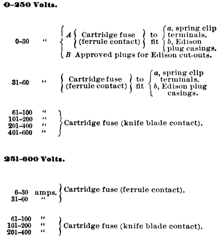
g. Dimensions.—Cartridge enclosed fuses and corresponding cut-out blocks must conform to the dimensions given in the table attached.
TABLE OF DIMENSIONS OF THE NATIONAL ELECTRICAL CODE
STANDARD CARTRIDGE ENCLOSED FUSE
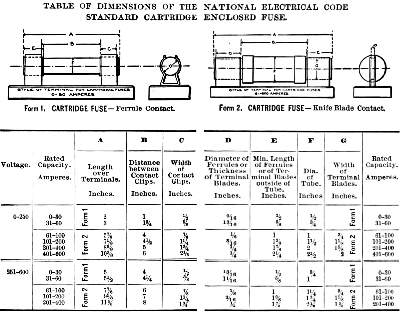
h. Rating.—Fuses must be so constructed that with the surrounding atmosphere at a temperature of 75 degrees Fahrenheit they will carry indefinitely a current 10 per cent greater than that at which they are rated, and at a current 25 per cent greater than the rating, they will open the circuit without reaching a temperature which will injure the fuse tube or terminals of the fuse block. With a current 50 per cent greater than the rating and at room temperature of 75 degrees Fahrenheit, the fuses, starting cold, must blow within the time specified.
| 0-30 amperes, | 30 seconds. |
|---|---|
| 31-60 " | 1 minute. |
| 61-100 " | 2 minutes. |
| 101-200 " | 4 " |
| 201-400 " | 8 " |
| 401-600 " | 10 " |
| i. Marking.—Must be marked, where it will be plainly visible, with the name or trade mark of the maker, the voltage and current for which the fuse is designed, and the words "National Electrical Code Standard." Each fuse must have a label, the color of which must be green for 250-volt fuses and red for 600-volt fuses. |
j. Temperature Rise.—The temperature of the exterior of the fuse enclosure must not rise more than 125 degrees Fahrenheit above that of the surrounding air when the fuse is carrying the current for which it is rated.
k. Test.—Must not hold an arc or throw out melted metal or sufficient flame to ignite easily inflammable material on or near the cut-out, when only one fuse is blown at a time on a short-circuit, on a system having a capacity of 300 K. W. or over, at the voltage for which the fuse is rated.
53 A. Tablet and Panel Boards.
The following minimum distance between bare live metal parts (bus-bars, etc.) must be maintained:—
| Between parts of opposite polarity, except at switches and link fuses. | Between parts of same polarity. | ||
|---|---|---|---|
| When mounted on the same surface. | When held free in the air. | At link fuses. | |
| 0-125 volts | ¾ inch. | ½ inch. | ½ inch. |
| 126-250 volts | 1¼ " | ¾ " | ¾ " |
54. Cut-Out Cabinets.
a. Material.—Cabinets must be substantially constructed of non-combustible, non-absorptive material, or of wood. When wood is used the inside of the cabinet must be completely lined with a non-combustible insulating material. Slate or marble at least one-quarter inch in thickness is strongly recommended for such lining, but, except with metal conduit systems, asbestos board at least one-eighth inch in thickness may be used in dry places if firmly secured by shellac and tacks. With metal conduit systems the lining of either the box or the gutter must be of one-sixteenth inch galvanized, painted or enameled iron, or preferably one-quarter inch slate or marble.
b. Door.—The door must close against a rabbet, so as to be perfectly dust-tight. Strong hinges and a strong hook or catch are required. Glass doors must be glazed with heavy glass, not less than 1-8 inch in thickness, and panes should not exceed 300 square inches in area. A space of at least two inches must be allowed between the fuses and the door. This is necessary to prevent cracking or breaking by the severe blow and intense heat which may be produced under some conditions.
c. Bushings.— Bushings through which wires enter must fit tightly the holes in the box, and must be of approved construction. The wires should completely fill the holes in the bushings, using tape to build up the wire, if necessary, so as to keep out the dust.
54 A. Rosettes.
a. Base.—Current-carrying parts must be mounted on non-combustible, non-absorptive insulating bases. There should be no openings through the rosette base except those for the supporting screws and in the concealed type for the conductors also, and these openings should not be made any larger than necessary. There must be at least 1-4 inch space, measured over the surface, between supporting screws and current-carrying parts. The supporting screws must be so located or countersunk that the flexible cord cannot come in contact with them. Bases for the knob and cleat type must have at least two holes for supporting screws; must be high enough to keep the wires and terminals at least 1-2 inch from the surface to which the rosette is attached, and must have a porcelain lug under each terminal to prevent the rosette from being placed over projections which would reduce the separation to less than 1-2 inch. Bases for the moulding and conduit box types must be high enough to keep the wires and terminals at least 3-8 inch from the surface wired over.
b. Mounting.—Contact pieces and terminals must be secured in position by at least two screws, or made with a square shoulder, or otherwise arranged to prevent turning. The nuts or screw heads on the under side of the base must be countersunk not less than 1-8 inch and covered with a waterproof compound which will not melt below 150 deg. Fahr.
c. Terminals.—Line terminal plates must be at least .07 inch in thickness, and terminal screws must not be smaller than No. 6 standard screw with about 32 threads per inch. Terminal plates for the flexible cord and for fuses must be at least .06 inch in thickness, and the terminal screws must not be smaller than No. 5 standard screw with about 40 threads per inch.
d. Cord Inlet.—The diameter of the cord inlet hole should measure 13-32 inch in order that standard portable cord may be used.
e. Knot Space.—Ample space must be provided for a substantial knot tied in the cord as a whole. All parts of the rosette upon which the knot is likely to bear must be smooth and well rounded.
f. Cover.—When the rosette is made in two parts, the cover must be secured to the base so that it will not work loose. In fused rosettes, the cover must fit closely over the base so as to prevent the accumulation of dust or dirt on the inside, and also to prevent any flash or melted metal from being thrown out when the fuses melt.
g. Markings.—Must be plainly marked where it may readily be seen after the rosette has been installed, with the name or trade mark of the manufacturer, and the rating in amperes and volts. Fuseless rosettes may be rated 3 amperes, 250 volts; fused rosettes, with link fuses, not over 2 amperes, 125 volts.
h. Test.—Fused rosettes must have a fuse in each pole and must operate successfully when short-circuited on the voltage for which they are designed, the test being made with the two fuses in circuit.
55. Sockets.
(For installation rules, see No. 27.)
a. Standard Sizes.—The standard lamp socket must be suitable for use on any voltage not exceeding 250 and with any size lamp up to fifty candle-power. For lamps larger than fifty candlepower a standard keyless socket may be used, or if a key is required, a special socket designed for the current to be used must be made. Any special sockets must follow the general spirit of these specifications.
b. Marking.—The standard socket must be plainly marked 250 v., 50 c. p., and with the manufacturer's name or registered trade mark. Special sockets must be marked with the current and voltage for which they are designed.
c. Shell.—Metal used for shells must be moderately hard, but not hard enough to be brittle or so soft as to be easily dented or knocked out of shape. Brass shells must be at least thirteen one-thousandths of an inch in thickness, and shells of any other material must be thick enough to give the same stiffness and strength as the required thickness of brass.
d. Lining.—The inside of the shells must be lined with insulating material, which must absolutely prevent the shell from becoming a part of the circuit, even though the wires inside the socket should start from their position under the binding screws. The material used for lining must be at least one thirty-second of an inch in thickness, and must be tough and tenacious. It must not be injuriously affected by the heat from the largest lamp permitted in the socket, and must leave water in which it is boiled practically neutral. It must be so firmly secured to the shell that it will not fall out with ordinary handling of the socket. It is preferable to have the lining in one piece.
e. Cap.—Caps, when of sheet brass, must be at least thirteen one-thousandths of an inch in thickness, and when cast or made of other metals must be of equivalent strength. The inlet piece, except for special sockets, must be tapped with a standard one-eighth-inch pipe thread. It must contain sufficient metal for a full, strong thread, and when not in one piece with the cap, must be joined to it in such a way as to give the strength of a single piece. There must be sufficient room in the cap to enable the ordinary wireman to easily and quickly make a knot in the cord and to push it into place in the cap without crowding. All parts of the cap upon which the knot is likely to bear must be smooth and well insulated.
f. Frame and Screws.—The frame which holds the moving parts must be sufficiently heavy to give ample strength and stiffness. Brass pieces containing screw threads must be at least six one-hundredths of an inch in thickness. Binding post screws must not be smaller than No. 5 standard screw with about 40 threads per inch.
g. Spacing.—Points of opposite polarity must everywhere be kept not less than three sixty-fourths of an inch apart, unless separated by a reliable insulation.
h. Connections.—The connecting points for the flexible cord must be made to very securely grip a No. 16 or 18 B. & S. gage conductor. A turned-up lug, arranged so that the cord may be gripped between the screw and the lug in such a way that it cannot possibly come out, is strongly advised.
i. Lamp Holder.—The socket must firmly hold the lamp in place so that it cannot be easily jarred out, and must provide a contact good enough to prevent undue heating with the maximum current allowed. The holding pieces, springs, and the like, if a part of the circuit, must not be sufficiently exposed to allow them to be brought in contact with anything outside of the lamp and socket.
j. Base.—With the exception of the lining, all parts of insulating material inside the shell must be made of porcelain.
k. Key.—The socket key-handle must be of such a material that it will not soften from the heat of a fifty candle-power lamp hanging downwards from the socket in air at 70 degrees Fahrenheit, and must be securely, but not necessarily rigidly, attached to the metal spindle which it is designed to turn.
l. Sealing.—All screws in porcelain pieces, which can be firmly sealed in place, must be so sealed by a waterproof compound which will not melt below 200 degrees Fahrenheit.
m. Putting Together.—The socket as a whole must be so put together that it will not rattle to pieces. Bayonet joints or an equivalent are recommended.
n. Test.—The socket, when slowly turned "on and off" at the rate of about two or three times per minute, while carrying a load of one ampere at 250 volts, must "make and break" the circuit 6,000 times before failing.
o. Keyless Sockets.— Keyless sockets of all kinds must comply with the requirements for key sockets as far as they apply.
p. Sockets of Insulating Material.—Sockets made of porcelain or other insulating material must conform to the above requirements as far as they apply, and all parts must be strong enough to withstand a moderate amount of hard usage without breaking.
q. Inlet Bushing.— When the socket is not attached to a fixture, the threaded inlet must be provided with a strong insulating bushing having a smooth hole at least nine thirty-seconds of an inch in diameter. The edges of the bushing must be rounded and all inside fins removed, so that in no place will the cord be subjected to the cutting or wearing action of a sharp edge.
56. Hanger-Boards for Series Arc Lamps.
a. Hanger-boards must be so constructed that all wires and current-carrying devices thereon will be exposed to view and thoroughly insulated by being mounted on a non-combustible, non-absorptive insulating substance. All switches attached to the same must be so constructed that they shall be automatic in their action, cutting off both poles to the lamp, not stopping between points when started and preventing an arc between points under all circumstances.
57. Arc Lamps.
(For installation rules, see Nos. 19 and 29.)
a. Must be provided with reliable stops to prevent carbons from falling out in case the clamps become loose.
b. All exposed parts must be carefully insulated from the circuit.
c. Must, for constant-current systems, be provided with an approved hand switch, and an automatic switch that will shunt the current around the carbons, should they fail to feed properly. The hand switch to be approved, if placed anywhere except on the lamp itself, must comply with requirements for switches on hanger-boards as laid down in No. 56.
58. Spark Arresters.
(For installation rules, see Nos. 19 c and 29 c.)
a. Spark arresters must so close the upper orifice of the globe that it will be impossible for any sparks, thrown off by the carbons, to escape.
59. Insulating Joints.
(See No. 26 a.)
a. Must be entirely made of material that will resist the action of illuminating gases, and will not give way or soften under the heat of an ordinary gas flame or leak under a moderate pressure. Must be so arranged that a deposit of moisture will not destroy the insulating effect; must show a dielectric strength between gas-pipe attachments sufficient to resist throughout five minutes the application of an electro-motive force of 4000 volts; and must be sufficiently strong to resist the strain to which they are liable to be subjected during installation.
b. Insulating joints having soft rubber in their construction will not be approved.
60. Rheostats.
(For installation rules, see Nos. 4 a and 8 c.)
a. Materials.—Must be made entirely of non-combustible materials except such minor parts as handles, magnet insulation, etc. All segments, lever arms, etc., must be mounted on non-combustible, non-absorptive, insulating material.
b. Construction.—Must have legs which will keep the current-carrying parts at least one inch from the surface on which the rheostat is mounted. The construction throughout must be heavy, rugged, and thoroughly workmanlike.
c. Connections.—Clamps for connecting wires to the terminals must be of a design which will ensure a thoroughly good connection, and must be sufficiently strong and heavy to withstand considerable hard usage. For currents above fifty amperes, lugs firmly screwed or bolted to the terminals, and into which the connecting wires shall be soldered, must be used.
d. Marking.—Must be plainly marked, where it may be readily seen after the device is installed, with the rating and the name of the maker; and the terminals of motor-starting rheostats must be marked to indicate to what part of the circuit each is to be connected, as "line," "armature," and "field."
e. Contacts.—The design of the fixed and movable contacts and the resistance in each section must be such as to secure the least tendency towards arcing and roughening of the contacts, even with careless handling or the presence of dirt. In motor-starting rheostats, the contact at which the circuit is broken by the lever arm when moving from the running to the starting position, must be so designed that there will be no detrimental arcing. The final contact, if any, on which the arm is brought to rest in the starting position must have no electrical connection.
f. No-voltage release.—Motor-starting rheostats must be so designed that the contact arm cannot be left on intermediate segments, and must be provided with an automatic device which will interrupt the supply circuit before the speed of the motor falls to less than one third of its normal value.
g. Overload-release.—Overload-release devices which are inoperative during the process of starting a motor will not be approved, unless other circuit-breakers or fuses are installed in connection with them.
h. Test.—Must, after 100 operations under the most severe normal conditions for which the device is designed, show no serious burning of the contacts or other faults, and the release mechanism of motor-starting rheostats must not be impaired by such a test. Field rheostats, or main-line regulators intended for continuous use, must not be burned out or depreciated by carrying the full normal current on any step for an indefinite period. Regulators intended for intermittent use (such as on electric cranes, elevators, etc.) must be able to carry their rated current on any step for as long a time as the character of the apparatus which they control will permit them to be used continuously.
61. Reactive Coils and Condensers.
a. Reactive coils must be made of non-combustible material, mounted on non-combustible bases and treated, in general, as sources of heat.
b. Condensers must be treated like other apparatus operating with equivalent voltage and currents. They must have non-combustible cases and supports, and must be isolated from all combustible materials and, in general, treated as sources of heat.
62. Transformers.
(For installation rules, see Nos. 11, 13, 13 A and 36.)
a. Must not be placed in any but metallic or other non-combustible cases.
b. Must be constructed to comply with the following tests:—
- Shall be run for eight consecutive hours at full load in watts under conditions of service, and at the end of that time the rise in temperature, as measured by the increase of resistance of the primary coil, shall not exceed 135 degrees Fahrenheit.
- The insulation of transformers when heated shall withstand continuously for five minutes a difference of potential of 10,000 volts (alternating) between primary and secondary coils and between the primary coils and core, and a no-load "run" at double voltage for thirty minutes.
63. Lightning Arresters.
(For installation rules, see No. 5.)
a. Lightning arresters must be of approved construction. (See list of Electrical Fittings.)
Class E.
MISCELLANEOUS.
64. Signaling Systems.
Governing wiring for telephone, telegraph, district messenger and call-bell circuits, fire and burglar alarms, and all similar systems which are hazardous only because of their liability to become crossed with electric light, heat, or power circuits.
When the entire circuit from Central Station to building is run in underground conduits, Sections a to m inclusive do not apply.
a. Outside wires should be run in underground ducts or strung on poles, and, as far as practicable, kept off of buildings, and must not be placed on the same cross-arm with electric light or power wires. They should not occupy the same duct, manhole or handhole of conduit systems with electric light or power wires.
b. When outside wires are run on same pole with electric light or power wires, the distance between the two inside pins of each cross-arm must not be less than twenty-six inches.
c. Where wires are attached to the outside walls of buildings they must have an approved rubber insulating covering (see No. 41), and on frame buildings or frame portions of other buildings shall be supported on glass petticoat insulators, or porcelain knobs.
d. The wires from last outside support to the cut-outs or protectors must be of copper, and must have an approved rubber insulation (see No. 41); must be provided with drip loops immediately outside the building and at entrance; must be kept not less than two and one-half inches apart.
e. Wires must enter building through approved non-combustible, non-absorptive, insulating bushings sloping upward from the outside.
Installations where the Current Carrying Parts of the Apparatus Installed are Capable of Carrying Indefinitely a Current of Ten Amperes.
f. An all-metallic circuit shall be provided, except in telegraph systems.
g. At the entrance of wires to buildings, approved single pole cut-outs, designed for 251-600 volts potential and containing fuses rated at not over ten amperes capacity, shall be provided for each wire. These cut-outs must not be placed in the immediate vicinity of easily ignitible stuff, or where exposed to inflammable gases, or dust or to flyings of combustible material.
h. The wires inside building shall be of copper not less than No. 16 B. & S. gage, and must have insulation and be supported, the same as would be required for an installation of electric light or power wiring, 0-550 volts potential.
i. The instruments shall be mounted on bases constructed of non-combustible, non-absorptive, insulation material. Holes for the supporting screws must be so located, or countersunk, that there will be at least one half of an inch space, measured over the surface, between the head of the screw and the nearest live metal part.
Installations where the Current Carrying Parts of the Apparatus Installed are Not Capable of Carrying Indefinitely a Current of Ten Amperes.
j. Must be provided with an approved protective device located as near as possible to the entrance of wires to building. The protector must not be placed in the immediate vicinity of easily ignitible stuff, or where exposed to inflammable gases or dust or flyings of combustile material.
k. Wires from entrance to building to protector must be supported on porcelain insulators, so that they will come in contact with nothing except their designed supports.
l. The ground wire of the protective device shall be run in accordance with the following requirements:—
- Shall be of copper, and not smaller than No. 18 B. & S. gage.
- Must have an approved rubber insulating covering (see No. 41).
- Must run in as straight a line as possible to a good permanent ground. This may be obtained by connecting to a water or gas pipe connected to the street mains and in service, or to a ground rod or pipe driven in permanently damp earth. When connections are made to pipes, preference shall be given to water pipes. If attachment is made to gas pipe, the connection in all cases must be made between the meter and the street mains. In every case the connection shall be made as near as possible to the earth.
- When the ground wire is attached to water or gas pipes, these pipes shall be thoroughly cleaned and tinned with rosin flux solder, if such a method is practicable; the ground wire shall then be wrapped tightly around the pipe and thoroughly soldered to it.
- When the above method is impracticable, then if there are fittings where a brass plug can be inserted, the ground wire shall be thoroughly soldered to it; if there are no such fittings, then the pipe shall be thoroughly cleaned and an approved ground clamp fastened to an exposed portion of the pipe and the ground wire well soldered to the ground clamp.
- When the ground wire is attached to a ground rod driven into the earth, the ground wire shall be soldered to the rod in a similar manner.
- Steam or hot-water pipes must not be used for a protector ground.
m. The protector to be approved must comply with the following requirements:—
For Instrument Circuits of Telegraph Systems.
- An approved single pole cut-out, in each wire, designed for 2,000 volts potential, and containing fuses rated at not over one ampere capacity. When main line cut-outs are installed as called for in section g, the instrument cut-outs may be placed between the switch board and the instrument as near the switch board as possible.
For All Other Systems.
- Must be mounted on non-combustible, non-absorptive insulating bases, so designed that when the protector is in place, all parts which may be alive will be thoroughly insulated from the wall to which the protector is attached.
- Must have the following parts:—
- A lightning arrester which will operate with a difference of potential between wires of not over 500 volts, and so arranged that the chance of accidental grounding is reduced to a minimum.
- A fuse designed to open the circuit in case the wires become crossed with light or power circuits. The fuse must be able to open the circuit without arcing or serious flashing when crossed with any ordinary commercial light or power circuit.
- A heat coil, if the sensitiveness of the instrument demands it, which will operate before a sneak current can damage the instrument the protector is guarding.
- The fuses must be so placed as to protect the arrester and heat coils, and the protector terminals must be plainly marked "line," "instrument," "ground."
The Following Rules Apply to All Systems whether the Wires from the Central Office to the Building are Overhead or Underground.
n. Wires beyond the protector, or wires inside buildings where no protector is used, must be neatly arranged and securely fastened in place in some convenient, workmanlike manner. They must not come nearer than six inches to any electric light or power wire in the building unless encased in approved tubing so secured as to prevent its slipping out of place.
o. Wires where bunched together within any building must have fire-resisting covering, or else be encased in a non-combustible tube or shaft.
- They must not be in the same tube with electric light or power wires, and if in the same shaft must be kept at least two inches from such wires. Ducts or shafts for wires must be of fireproof construction and thoroughly "stopped" at each floor or wall.
65. Electric Gas Lighting.
a. Electric gas lighting must not be used on the same fixture with the electric light.
65 A. Moving Picture Machines.
a. Top reel must be encased in an iron box with hole at the bottom only large enough for film to pass through, and cover so arranged that this hole can be instantly closed. No solder to be used in the construction of this box.
b. A box must be used for receiving the film after being shown, made of galvanized iron with a hole in the top only large enough for the film to pass through freely, with a cover so arranged that this hole can be instantly closed. An opening may be placed at the side of the box to take the film out, with a door hung at the top, so arranged that it cannot be entirely opened, and provided with a spring catch to lock it closed. No solder to be used in the construction of this box.
c. The handle or crank used in operating the machine must be secured to the spindle or shaft so that there will be no liability of its coming off and allowing the film to stop in front of the lamp.
d. A shutter must be placed in front of the condenser, arranged so as to be normally closed, and held open by pressure of the foot.
e. A metal pan must be placed under the arc lamp to catch all sparks.
f. Extra films must be kept in metal box with tight-fitting covers.
66. Insulation Resistance.
The wiring in any building must test free from grounds; i. e., the complete installation must have an insulation between conductors and between all conductors and the ground (not including attachments, sockets, receptacles, etc.) not less than that given in the following table:—
| Up to 5 amperes | 4,000,000 ohms. |
|---|---|
| Up to 10 amperes | 2,000,000 ohms. |
| Up to 25 amperes | 800,000 ohms. |
| Up to 50 amperes | 400,000 ohms. |
| Up to 100 amperes | 200,000 ohms. |
| Up to 200 amperes | 100,000 ohms. |
| Up to 400 amperes | 50,000 ohms. |
| Up to 800 amperes | 25,000 ohms. |
| Up to 1,600 amperes | 12,500 ohms. |
| The test must be made with all cut-outs and safety devices in place. If the lamp sockets, receptacles, electroliers, etc., are also connected, only one half of the resistances specified in the table will be required. |
67. Soldering Fluid.
a. The following formula for soldering fluid is suggested:—
| Saturated solution of zinc chloride | 5 parts |
|---|---|
| Alcohol | 4 parts |
| Glycerine | 1 part |
Class F.
MARINE WORK.
68. Generators.
a. Must be located in a dry place.
b. Must have their frames insulated from their bed-plates.
c. Must each be provided with a waterproof cover.
d. Must each be provided with a name-plate, giving the maker's name, the capacity in volts and amperes, and the normal speed in revolutions per minute.
69. Wires.
a. Must be supported in approved moulding or conduit, except at switchboards and for portables.
b. Must have no single wire larger than No. 12 B. & S. gage. Wires to be stranded when greater carrying capacity is required. No single solid wire smaller than No. 14 B. & S. gage, except in fixture wiring, to be used.
c. Splices or taps in conductors must be avoided as far as possible. Where it is necessary to make them they must be so spliced or joined as to be both mechanically and electrically secure without solder. They must then be soldered, to insure preservation, covered with an insulating compound equal to the insulation of the wire, and further protected by a waterproof tape. The joint must then be coated or painted with a waterproof compound.
For Moulding Work.
d. Must have an approved insulating covering.
e. Must have, when passing through water-tight bulkheads and through all decks, a metallic stuffing tube lined with hard rubber. In case of deck tubes, they shall be boxed near deck to prevent mechanical injury.
f. Must be bushed with hard rubber tubing, one eighth of an inch in thickness, when passing through beams and non-water-tight bulkheads.
For Conduit Work.
g. Must have an approved insulating covering.
For unlined metal conduits, conductors must conform to the specifications given for lined conduits, and in addition have a second outer fibrous covering at least one thirty-second of an inch in thickness, and sufficiently tenacious to withstand the abrasion of being hauled through the metal conduit.
h. Must not be drawn in until the mechanical work on the conduit is completed and same is in place.
i. Where run through coal bunkers, boiler rooms, and where they are exposed to severe mechanical injury, must be encased in approved conduit.
70. Portable Conductors.
a. Must be made of two stranded conductors, each having a carrying capacity equivalent to not less than No. 14 B. & S. gage wire, and each covered with an approved insulation and covering.
71. Bell or Other Wires.
a. Shall never be run in same duct with lighting or power wires.
72. Table of Capacity of Wires.
| B. & S. G. | Area Actual C. M. | No. of Strands. | Size of Strands B. & S. G. | Amperes. |
|---|---|---|---|---|
| 19 | 1,288 | .. | .. | .. |
| 18 | 1,624 | .. | .. | 3 |
| 17 | 2,048 | .. | .. | .. |
| 16 | 2,583 | .. | .. | 6 |
| 15 | 3,257 | .. | .. | .. |
| 14 | 4,107 | .. | .. | 12 |
| 12 | 6,530 | .. | .. | 17 |
| .. | 9,016 | 7 | 19 | 21 |
| .. | 11,368 | 7 | 18 | 25 |
| .. | 14,336 | 7 | 17 | 30 |
| .. | 18,081 | 7 | 16 | 35 |
| .. | 22,799 | 7 | 15 | 40 |
| .. | 30,856 | 19 | 18 | 50 |
| .. | 38,912 | 19 | 17 | 60 |
| .. | 49,077 | 19 | 16 | 70 |
| .. | 60,088 | 37 | 18 | 85 |
| .. | 75,776 | 37 | 17 | 100 |
| .. | 99,064 | 61 | 18 | 120 |
| .. | 124,928 | 61 | 17 | 145 |
| .. | 157,563 | 61 | 16 | 170 |
| .. | 198,677 | 61 | 15 | 200 |
| .. | 250,527 | 61 | 14 | 235 |
| .. | 296,387 | 91 | 15 | 270 |
| .. | 373,737 | 91 | 14 | 320 |
| .. | 413,639 | 127 | 15 | 340 |
73. Switchboard.
a. Must be made of non-combustible, non-absorptive insulating material, such as marble or slate.
b. Must be kept free from moisture, and must be located so as to be accessible from all sides.
c. Must have a main switch, main cut-out and ammeter for each generator. Must also have a voltmeter and ground detector.
d. Must have a cut-out and switch for each side of each circuit leading from board.
74. Resistance Boxes.
(For construction rules, see No. 60.)
a. Must be located on switchboard or away from combustible material. When not placed on switchboard they must be mounted on non-inflammable, non-absorptive insulating material.
75. Switches.
(For construction rules, see No. 51.)
a. Must not be single pole when the circuits which they control supply devices which require over 660 watts of energy.
b. When exposed to dampness, they must be enclosed in a water-tight case.
c. Must be of the knife pattern when located on switchboard.
d. Must be provided so that each freight compartment may be separately controlled.
76. Cut-Outs.
(For construction rules, see No. 52.)
a. Must be placed at every point where a change is made in the size of the wire (unless the cut-out in the larger wire will protect the smaller).
b. In places such as upper decks, holds, cargo spaces and fire-rooms, a water-tight and fireproof cut-out may be used, connecting directly to mains when such cut-out supplies circuits requiring not more than 660 watts energy.
c. When placed anywhere except on switchboards and certain places, as cargo spaces, holds, fire-rooms, etc., where it is impossible to run from center of distribution, they shall be in a cabinet lined with fire-resisting material.
d. Except for motors, searchlights and diving lamps shall be so placed that no group of lamps, requiring a current of more than 660 watts, shall ultimately be dependent upon one cut-out.
77. Fixtures.
a. Shall be mounted on blocks made from well-seasoned lumber treated with two coats of white lead or shellac.
b. Where exposed to dampness, the lamp must be surrounded by a vapor-proof globe.
c. Where exposed to mechanical injury, the lamp must be surrounded by a globe protected by a stout wire guard.
d. Shall be wired with same grade of insulation as portable conductors which are not exposed to moisture or mechanical injury.
e. Ceiling fixtures over two feet in length must be provided with stay chains.
78. Sockets.
(For construction rules, see No. 55.)
79. Wooden Mouldings.
(For construction rules, see No. 50.)
a. Where moulding is run over rivets, beams, etc., a backing strip must first be put up and the moulding secured to this.
b. Capping must be secured by brass screws.
80. Interior Conduits.
(For installation rules, see No. 25.)
(For construction rules, see No. 49.)
81. Signal Lights.
a. Must be provided with approved telltale board, located preferably in pilot-house, which will immediately indicate a burned-out lamp.
82. Motors.
a. Must be wired under the same precautions as with a current of same volume and potential for lighting. The motor and resistance box must be protected by a double-pole cut-out and controlled by a double-pole switch, except in cases where one-quarter horse power or less is used.
b. Must be thoroughly insulated. Where possible, should be set on base frames made from filled, hard, dry wood and raised above surrounding deck. On hoists and winches they shall be insulated from bed-plates by hard rubber, fiber or similar insulating material.
c. Shall be covered with a waterproof cover when not in use.
d. Must each be provided with a name-plate giving maker's name, the capacity in volts and amperes, and the normal speed in revolutions per minute.
83. Insulation Resistance.
The wiring in any vessel must test free from grounds; i. e., the complete installation must have an insulation between conductors and between all conductors and the ground (not including attachments, sockets, receptacles, etc.) of not less than the following:—
| Up to 25 amperes | 800,000 ohms. |
|---|---|
| Up to 50 amperes | 400,000 ohms. |
| Up to 100 amperes | 200,000 ohms. |
| Up to 200 amperes | 100,000 ohms. |
| Up to 400 amperes | 50,000 ohms. |
| Up to 800 amperes | 25,000 ohms. |
| Up to 1,600 amperes | 12,500 ohms. |
| All cut-outs and safety devices in place in the above. |
Where lamp sockets, receptacles and electroliers, etc., are connected, one half of the above will be required.
INDEX.
| NUMBER AND SECTION | |
|---|---|
| Acid fumes | 10 (c) & 24 (i) to 24 (k) |
| Arc lamps, Construction of | 57 |
| Arc lamps, location requirements | 19 (c) & 29 (c) |
| Arc lamps on constant-current systems | 19 |
| Arc lamps on constant-potential systems | 29 |
| Armored Cable, Construction of | 24 A (d) & 48 |
| Armored Cable, Installation of | 24 (s) & 24 A |
| Armored Cable, Metallic sheaths to be grounded | 12 (i) & 24 A (c) |
| Attendance | 6 |
| Balancing coils on three-wire systems | (See Reactive Coils.) |
| Base-frames for generators and motors | 1 (c) & 8 (a) |
| Batteries, Storage and primary | 10 |
| Bell wires | 64 |
| Binding screws not to bear strain | 28 (g) |
| Blocks at fixture and switch outlets | 22 (e) |
| Bonds required on rails in car houses | 33 (g) |
| Boxing for wires. | (See Protection for Wires.) |
| Burglar alarms | 64 |
| Burrs and fins in fixtures | 26 (b) |
| Bus-bars | 2 (b) & 3 (e) |
| Bushings at entrances to buildings | 12 (g) & 64 (e) |
| Bushings for lamp sockets | 28 (f) & 55 (q) |
| Bushings for wires, Construction of | 50 A |
| Bushings inside of buildings | 14 (d) |
| Cabinets, cut-out and switch, Construction | 17 (d), 24 (a) & 54 |
| Cabinets, cut-out and switch, Use | 17 (b) to 17 (d), 21 (c) & 22 (b) |
| Cabinets for rheostats and auto-starters, where required | 8 (d) |
| Cable, Armored | (See Armored Cable.) |
| Car houses | 33 |
| Car wiring and equipment | 32 |
| Care and attendance | 6 |
| Carrying capacity of wires, Table of | 16 |
| Ceiling rosettes, Construction of | 54 A |
| Ceiling rosettes, Use of | 21 (d) |
| Central stations | 1 to 7 |
| Circuit-breakers, Construction of | 52 (a), 52 (d) & 52 (e) |
| Circuit-breakers, how high may be set | 21 (e) |
| Circuit-breakers, Installation of | 17 & 21 |
| Circuit-breakers, where required | 8 (d) & 9 |
| Cleats, Construction of | 50 B |
| Compensator coils for arc lamps | 30 |
| Compensator coils for three-wire systems | (See Reactive Coils.) |
| Concealed "knob and tube" work | 24 (q) to 24 (u) |
| Concentric wire | 47 (c) |
| Condensers | 61 (b) |
| Conductors | (See Wires.) |
| Conduit wire, Construction of | 47 |
| Conduit wiring | 24 (n) to 24 (p) |
| Conduits, metal, Construction of | 49 |
| Conduits, metal, Installation of | 23 |
| Constant-current systems | 18 to 20 |
| Constant-potential systems, general rules | 21 to 23 |
| Converters. | (See Transformers.) |
| Crossing of constant-potential pole-lines, over 5,000 volts | 12 A (d) |
| Cut-outs, Construction of, open link fuse | 52 (f) to 52 (l) |
| Cut-outs, Construction of, enclosed fuse | 52 (m) to 52 (s) |
| Cut-outs, Installation of | 17 & 21 |
| Cut-outs must protect all wires of the circuit | 17 (a) |
| Cut-outs, Number of lights allowed to one | 21 (d) & 31 (a) |
| Cut-outs, where required | 1 (d), 2 (d), 8 (c), 21 (a), 21 (b) & 29 (a) |
| Damp places | 14 (f), 17 (c), 24 (i) to 24 (k) & 27 (b) |
| Decorative series incandescent lamps | 31 |
| Distance between conductors, inside work | 18 (d), 24 (h), 24 (j), 24 (r) & 35 (c) |
| Distance between conductors, outside work | 12 (b), 12 A (c) & 12 A (d) (2) |
| Drip loops at entrances to buildings | 12 (g) & 64 (d) |
| Dynamo rooms | 1 to 7 |
| Economy coils for arc lamps | 30 |
| Electric gas lighting | 65 |
| Electric heaters | 23 |
| Electrolytic corrosion of underground metal work | 12 (n) |
| Electro-magnetic devices for switches not approved | 20 (c) |
| Emergency switches | note to 22 (a) |
| Enclosed arc lamps | 19 (c) & 29 (c) |
| Equalizers, Installation of | 4 |
| Extra-high constant-potential systems | 38 & 39 |
| Fan motors hung from ceilings | 8 (g) |
| Feeders, Railway | 33 (f) |
| Fished wires | 24 (c) & 24 (s) |
| Fittings, List of approved | (See inside of front cover.) |
| Fittings, materials and details of construction | 40 to 63 |
| Fixture canopies | 24 (w) and 26 (a) |
| Fixtures | 26 |
| Fixture wire | 46 |
| Fixture wiring | 24 (v) to 24 (y) |
| Flexible cord, Construction of, general rule | 45 (a) |
| Flexible cord for heating apparatus, Construction of | 45 (g) |
| Flexible cord for pendant lamps, Construction of | 45 (b) to 45 (e) |
| Flexible cord for portable use, Construction of | 45 (f) |
| Flexible cord, Use of | 28 |
| Flexible tubing, Construction of | 50 C |
| Flexible tubing, where permitted | 14 (d), 24 (s) & 24 (u) |
| Foreign currents, Protection against | 64 |
| Formula for soldering fluid | 67 |
| Fuses, Construction of, enclosed | 53 (d) to 53 (k) |
| Fuses, Construction of, open link type | 53 (a) to 53 (c) |
| Fuses, Installation of | 1 (d), 17 & 21 |
| Gas lighting, Electric | 65 |
| General plan of arrangement of rules | page 3 |
| General suggestions for electric work | page 4 |
| Generators | 1 |
| Ground connections for lightning arresters | 5 (c) & 64 (l) |
| Ground connections for low-potential circuits | 13 A, (c) to (g) |
| Ground detectors, where required | 7 (a) |
| Ground plates, construction of | 13 A, (g) |
| Ground return wires, trolley systems | 12 (n) |
| Grounded trolley circuits, Light and power from | 34 |
| Grounding dynamo and motor frames | 1 (c) & 8 (a) |
| Grounding interior conduits | 25 (f) |
| Grounding low-potential circuits | 13 A |
| Grounding sheaths of cables | 12 (i) |
| Grounds, Testing for | 7 |
| Guard irons or wires, Use of | 12 (d), 12 (m), 12 A, (d) |
| Guard strings, inside work, where required | 18 (e), & 24 (e) |
| Hanger-boards, Construction of | 56 |
| Heaters, Electric | 23 |
| High constant-potential systems | 35 to 37 |
| Incandescent lamps as resistances | 4 (b) & 29 (b) |
| Incandescent lamps in series | 20, 21 (d), 31 & 37 |
| Incandescent lamps, where inflammable gases exist | 27 (a) |
| Induction coils | (See Reactive Coils.) |
| Inside work | 14 to 39 |
| Insulated platforms, at high-potential machines | 1 (c) & 8 (a) |
| Insulating joints, Construction of | 59 |
| Insulating joints, when required | 26 (a) |
| Insulation of fixture canopies, when required | 26 (a) |
| Insulation of trolley wires | 12 (k) |
| Insulation resistance of completed systems | 66 |
| Insulator spacing, inside work | 24 (h), 24 (j), 24 (r) & 35 (c) |
| Joint pole crossing, high-pressure line | 12 A (d), (2) |
| Joints, in conductors | 12 (f) & 14 (c) |
| Junction boxes, Conduit, installation of | 24 A (f) & 25 (g) |
| Knob and tube work | 24 (q) to 24 (u) |
| Knots in flexible cord, required in sockets and rosettes | 28 (g) |
| Lamps | (See Arc Lamps and Incandescent Lamps.) |
| Lighting and power from railway wires | 34 |
| Lightning arresters, Construction of | 63 |
| Lightning arresters, Installation of | 5 |
| Low constant-potential systems | 24 to 34 |
| Lugs for terminal connections, when required | 14 (c), 51 (h), 52 (i), 52 (p) & 60 (c) |
| Marine work | 68 to 83 |
| Motor enclosures | 8 (f) |
| Motor equipments, 550 volt, voltage allowed at generator or transformer | note before 24 |
| Motors | 8 |
| Moulding, Construction of | 50 |
| Moulding, on brick walls | 24 (m) |
| Moulding, Wires in | 24 (l) & 24 (m) |
| Moving picture machines, Construction of | 65 A |
| Multiple-series systems, when permitted | 8 (e), 20 (c) & 29 (a) |
| Oily waste | 6 (b) |
| Open wiring | 24 (g) to 24 (k) |
| Outlet and switch boxes, Construction of | 49 A |
| Outlet boxes or plates, Conduit, when required | 24 A (b) & 25 (d) |
| Outside work | 12, 12 A, 13, 13 A & 64 |
| Panel boards, Construction of | 53 A |
| Pendants for use in hazardous places | 28 (d) |
| Pipe-hangers for incandescent lamps | 27 (a) |
| Pole-lines, Constant-potential, over 5,000 volts | 12 A |
| Pole-lines, High-pressure, near buildings | 12 A (e) |
| Portable heaters, conductors for | 45 (g) |
| Portable lamps, Installation of | 28 (d) |
| Portable lamps, motors, etc., conductors for | 45 (f) |
| Power, transformer and switch stations | 1 to 7 |
| Protection for gas outlet pipes | 26 (a) |
| Protection for motor equipments | 8 (d) |
| Protection for outlet wires | 24 (u) & 26 (a) |
| Protection for wires on side walls or columns | 18 (e), 24 (e) & 35 (d) |
| Protective devices on signal circuits, Construction of | 64 (m) |
| Protective devices on signal circuits, Installation of | 64 (g) to 64 (j) |
| Railway power plants | 9 |
| Railway wires | (See Trolley Wires.) |
| Reactive coils | 61 (a) |
| Resistance boxes | (See Rheostats.) |
| Resistances used with constant-potential arc lamps | 29 (b) |
| Rheostats, Construction of | 60 |
| Rheostats, Installation of | 4, 8 (c) & 8 (d) |
| Roof wiring | 12 |
| Rosettes, Construction of | 54 A |
| Rosettes, Use of | 21 (d) |
| Running-boards, Construction of | 18 (e) |
| Running-boards, where required | 18 (e), 24 (e) & 35 (d) |
| Screen of wires, at cross-over in high-pressure pole line, over 5,000 volts | 12 A (d) (3) |
| Series arc lamps | 19 |
| Series incandescent lamps | 20, 31, & 37 |
| Series-multiple systems, when permitted | 8 (e) & 20 (c) |
| Service wires, Underground | 15 (a), 15 (c), 15 (d) |
| Signaling systems | 64 |
| Sockets, Construction of | 55 |
| Sockets, Installation of | 27 |
| Soldering fluid, Formula for | 67 |
| Soldering stranded wires | 14 (c) & 19 (d) |
| Spark arresters, Construction of | 58 |
| Spark arresters, when required | 19 (c) & 29 (c) |
| Static electricity, due to belt friction | 1 (c) & 8 (a) |
| Stations and dynamo rooms | 1 to 7 |
| Stiff pendants for incandescent lamps | 27 (a) |
| Storage battery rooms | 10 |
| Strips for protecting inside wires | (See Guard Strips) |
| Switchboards | 3 |
| Switch boxes, Conduit, Construction of | 49 A |
| Switches, Construction of knife | 51 (c) to 51 (k) |
| Switches, Construction of, snap | 51 (l) to 51 (t) |
| Switches, Electro-magnetic, not approved | 20 (c) |
| Switches, Emergency | note to 22 (a) |
| Switches, Flush, Installation of | 22 (d) |
| Switches for constant-current systems | 18 (b) & 51 (b) |
| Switches in damp places | 17 (c) |
| Switches, Indicating, when required | 8 (c), 23 (b), 51 (a) & 51 (b) |
| Switches, Installation of | 17 & 22 |
| Switches must disconnect all wires of circuit | 17 (a) |
| Switches, Service | 18 (b), 22 (a) & 51 (a) |
| Switches, Single-pole, when permitted | 8 (c) & 22 (c) |
| Switches, Snap, when preferred | 22 (b) |
| Switches, Time | 17 (d) |
| Systems, Constant-current | 18 to 20 |
| Systems, Constant-potential, general rules | 21 to 23 |
| Systems, Extra-high constant potential | 38 & 39 |
| Systems, High constant-potential | 35 to 37 |
| Systems, Low constant-potential | 24 to 34 |
| Systems, Multiple-series | 8 (e) & 20 (c) |
| Systems, Series-multiple | 8 (e) & 20 (c) |
| Systems, Signaling | 64 |
| Tablet boards, Construction of | 53 A |
| Telegraph, telephone and signaling circuits | 64 |
| Testing for grounds | 7 |
| Testing for insulation resistance of completed systems | 66 |
| Three-pole cross-over for high-pressure line | 12 A (d-1) |
| Tie wires | 12 (a) & 14 (b) |
| Tinning of wires, when required | 41 (a) & 46 (b) |
| Transformers, Construction of | 62 |
| Transformers, grounding of secondaries | 13 A |
| Transformers, Installation of, inside | 11 & 36 |
| Transformers, Installation of, outside | 12 |
| Transformer stations | 1 to 7 |
| Transmission lines, constant-potential, over 5,000 volts | 12 A |
| Trolley circuits, Grounded, Light and power from | 34 |
| Trolley wires | 12 (j) to 12 (m) |
| Tubes, Insulating | (See Bushings.) |
| Tubing, Flexible | (See Flexible Tubing.) |
| Voltmeter, Switchboard, circuit for | 2 (d) |
| Waste, oily | 6 (b) |
| Waterproof construction | 24 (i) to 24 (k) |
| Waterproof pendants | 27 (b) |
| Wire, Concentric | 47 (c) |
| Wire, Conduit | 47 |
| Wire, Construction of, general rules | 46 |
| Wire, Fixture | 46 |
| Wire, Netting required on arc lamps | 19(c) & 29 (c) |
| Wire, Rubber-covered | 41 |
| Wire, Slow-burning | 43 |
| Wire, Slow-burning, weatherproof | 42 |
| Wire, Weatherproof | 44 |
| Wires, Carrying capacity table | 16 |
| Wires, Car Work | 32 |
| Wires, Concealed "knob and tube" work | 24 (q) to 24 (u) |
| Wires, Conduit work | 24 (n) to 24 (p) |
Errata
-
25(d) “Must be equipped at every outlet with an approved outlet box or plate (see No. 49 l to o).” - This reference is incorrect, and is referring to 49(A). Likely, 49(A)(a)-(g) was originally a continuation of No. 49, with subsections (l)-(r), and later changed to distinguish switch and outlet boxes from general conduit.
-
24(t) “Mixed concealed knob and tube work as provided for in No. 24 s, must comply with requirements of No. 24 [blank] to p…” The book that was scanned for this release appears to be missing the proper reference. It should read “No. 24 n to p”, referring to the Conduit Work section of “Wiring”. It doesn’t look like an error with the inking/stamping process to me, it looks like someone forgot to put the “n” in the original plate form. Curious to know if other 1905 owners have this error, as well.
-
46(e) Informational Note - Refers reader to No. 44 when talking about slow-burning wire, when they meant No. 43.
Insufficiencies in this restoration
- The inside of the front cover apparently has information about lists of approved fittings, but the scan I had access to did not have the original cover and didn’t include that information. Please reach out if you have access to that information.
Other observations:
-
The National Electrical Code at this time served the purpose of not just specifying installation methods, but construction methods, as well. The “listing” mechanism was not built out through UL or other third parties yet, so if you wanted to know if a cartridge fuse was built to spec or not, you’d reference No. 53 in the 1905 NEC. All of Class D is about product construction. They also specify that those kinds of products have the words “National Electrical Code Standard” on them, or “N. E. Code St’d” if there’s not room.
-
They also mandated the wiring practices inside of cars, which was still a nascent industry.
-
Fun observation - 65 A is an entire section on moving picture machines, not specifying special wiring, but focused entirely on making sure the arc lamps inside of film projectors don’t catch the films on fire.